


removal of nitrates
Reading time:Nitrates can be removed via either physical-chemical or biological methods.
physical-chemical processes – the azurion process
Reverse osmosis, electrodialysis and ion exchange are the processes that can be used to remove nitrates.
Neither reverse osmosis (see separation by membranes) nor electro dialysis (see dialysis membranes) are NO3- ion-specific and, therefore, are only used when desalination has to be carried out at the same time (brackish water).
Nitrate Removal using ion exchange and the resins that can be used to produce drinking water have been approved in a number of countries. Before embarking on any project, it is advisable to check the legislation applicable in the country concerned.
general utilisation conditions
The use of ion exchangers has to be assessed on the basis of several parameters:
- suspended solids content of the water to be treated: this content must be less than 1 mg·L–1. If this isn’t the case, removal of suspended solids will induce a major head loss, frequent washes and a prematurely spent resin;
- composition of the water: in addition to NO3- ions, ion exchange removes SO42—ions and some HCO3- ions which are exchanged for Cℓ– ions when the resin is regenerated using sodium chloride. In treated water, this can lead to an excessively high concentration of Cℓ– ions. Operating with an HCO3–exchange can provide a solution but this solution will be more difficult and more costly to implement.
Note 1: eluates created by the regeneration contain all the sulphates and nitrates from the raw water, some of the bicarbonate ions and a high proportion of sodium chloride used as a regenerating agent. The availability of an outlet for removing these eluates is absolutely essential.
Note 2: the advantage of ion exchange is that it can be used regardless of the temperature of the water to be treated.
utilisation
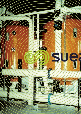
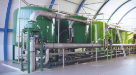
An illustration of the Azurion process application is provided by the Rest DWTP at Plouenan (France) that processes surface water on behalf of the Horn water board. Figure 38 provides a schematic diagram of the treatment train. An additional installation is illustrated in photo 24.
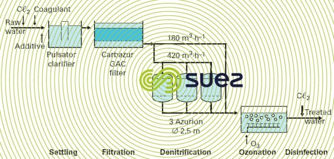

Eluates are stored in a lagoon during the dry season before being pumped out for dilution in the river during the rainy season.
The technology selected at Rest (France) for the actual ion exchange is the backflow regeneration system with a drained layer (air blocking); however, more recent plants use the UFD technique (see section mechanical blocking).
biological denitrification processes
general utilisation conditions
These techniques use attached growth. Trials have been carried out using autotrophic bacteria that will grow using, for instance, hydrogen or a sulphur-containing medium depending on the reactions:


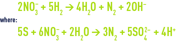
In the latter case, CaCO3 will be required to neutralise the acidity created.
Results have demonstrated that these bacteria have very slow growth kinetics: usable flow rates are low (0.5 to 2 m · h–1). Therefore, these techniques are not really applicable on a commercial scale.
The heterotrophic bacteria process is the most widely used (see also section nitrogen cycle and nitrogen conversion). These bacteria derive their energy from carbonaceous nutrients, mainly ethanol, according to the following overall reaction:

The main characteristics of this process are summarised as follows:
- conversion of nitrates into nitrogen gas;
- sludge (excess biomass) that can be processed after being mixed in with urban sludge;
- little effect on the water’s calcium-carbonate balance;
- temperature-sensitive process. It cannot be used easily when the temperature falls below 7-8°C;
- this process is sensitive to the presence of dissolved O2 in raw water (bacteria will consume free O2 before the O2 bound to the nitrates, thereby creating a greater consumption of carbonaceous nutrient);
- initial commissioning requires approximately one month.
utilisation – the Nitrazur DN process
This process is outlined in figure 39.
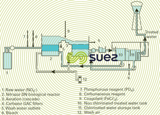
The Nitrazur DN reactor (see also section nitrogen conversion) operates in upflow mode, as a co-current with the nitrogen that is released, thereby avoiding the drawbacks induced by gas binding created by the nitrogen. Normal velocities range from 6 to 10 m·h–1, for a 3 m biolite depth.
In addition to the carbonaceous nutrient, phosphorous also has to be added at the intake (approximately 0.5 g of PO43– to eliminate 100 g of nitrates) as this is essential to bacterial development. Optimum pH will be in the region of 7.5.
In addition to its filtering effect, activated carbon also plays a polishing role where by the residual carbonaceous nutrient is eliminated biologically and any traces of pesticides that are frequently present with nitrates (when these are resulting from agricultural pollution) are also fixed. Ozone treatment can also be used to replace or supplement intermediate aeration.
Treatment is set to a target residual nitrate content in order to limit treatment cost and the overall amount of carbonaceous nutrient addition.
The reactor is flushed using non-chlorinated water. Bleach is introduced for disinfection purposes into the second storage tank.
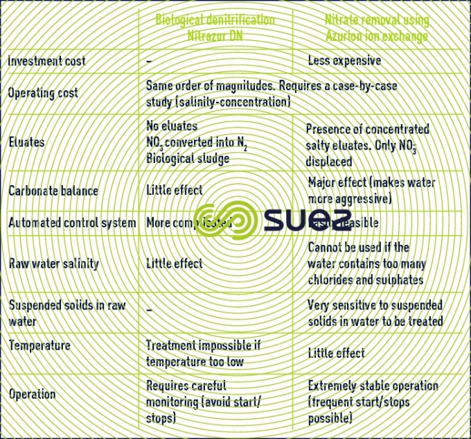
compared advantages of the two nitrate removal techniques
Bookmark tool
Click on the bookmark tool, highlight the last read paragraph to continue your reading later
