


clarification membranes
Reading time:These membranes have pores that are visible under electronic microscopes. Water moves through these pores by convection, dragging solutes and particles that are smaller than the pores (strainer effect).
As we shall see, these membranes are themselves classified as ultrafiltration and microfiltration membranes.
utrafiltration ( UF ) membranes
Organic ultrafiltration membranes include all asymmetric types whereas mineral membranes are composite membranes. They allow salts through freely and only reject the largest solutes (macromolecules) and particulate elements such as viruses, bacteria, colloids…
They are commonly characterized by their “cut off”: size of the smallest gramme-molecular weight protein of which more than 90% is screened out by the membrane. In this category, we find industrial membranes that have a cut off ranging from 2·103 to 4·105 Daltons.
The NFX45-103 Standard of December 1997, « Porous Membranes – Retention rate of ultrafiltration and nanofiltration membranes », provide a method for measuring the cut-off threshold. However this protocol can only be used for guidance, especially as the tracers used can become deformed under the effects of pressure and their steric configuration varies according to salinity, pH, etc. . Finally, the discharge rate varies significantly depending on operating conditions …
The unit outputs quoted for UF membranes range from 0.05 to 0.5 m3·h–1·m–2.bar for clean water. Warning: this output will decline considerably for two main reasons in the case of ultrafiltration membranes that have low cut off (<50 000 D): the concentration polarisation to which fouling has to be added when colloids are present.
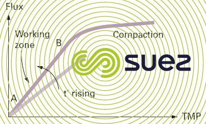
The first phenomenon was already discussed when examining reverse osmosis; in ultrafiltration, it is responsible for the appearance of a limit flux as the transmembrane pressure rises (figure 55) and this will even affect “new” membranes.

In fact, given the very poor backscatter involving macromolecules, polarisation coefficients often exceed 10.
Values observed for the flux will then only be in the region of a few tens of litres per m² and per hour.
The only means we have to increase this flux consists in working at higher tangential velocity, generating higher energy consumption.
As recorded above, these membranes behave like “desalination” membranes and, therefore, are not very much used in water treatment. On the contrary, in processes found in chemical, pharmaceutical and milk industries, where they are used to recover recyclable macromolecules (enzymes, proteins, antibiotics…).
In water treatment applications, the most frequently used membranes will be the “loose” membrane types with cut off of approximately 105Daltons or 0.03 to 0.01 μm pores that will only remove very few macromolecules (e.g. eliminating 10 to 20% of colour from water containing humic acids). Their role primarily consists in removing suspended solids whence the suggested designation of clarification membranes. In this case, the limit flux phenomenon no longer applies to new membranes but a second phenomenon appears: clogging that becomes largely preponderant. At constant concentrations and pressures, this phenomenon can be seen as a drop in flux over time, potentially leading to a complete fouling of the membrane.
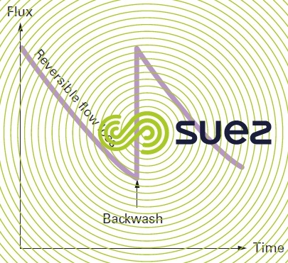
Fouling is caused by the formation of a layer of colloids on the membrane surface and also by various solutes being absorbed in the pores. The first of these phenomena is essentially reversible through backwashing (operation that consists in reversing pressures in order to send the produced water through the membrane and thus dislodge the deposit) (figure 56).
On the contrary, adsorption is very often insensitive to backwashing or to an increase in crosswashing velocity; the membrane can only be “cleaned” by means of a suitable chemical treatment.
In practice, in separation by membranes, we shall see that all ultrafiltration membranes used in water treatment are made of asymmetric hollow fibres, with an internal or external skin depending on whether this skin is on the outer or inner fibre side. The main reason is that this geometry allows for efficient low pressure backwashes without having to support the membrane mechanically.
microfiltration ( MF ) membranes
Microfiltration membranes are “coarser” and characterised by their 0.1 to 0.45 μm pores that enable them to eliminate “coarse” bacteria, protozoa and colloids but not viruses (save those attached to suspended solids) or the finer colloids (e.g. colloidal silica). On the other hand, their larger pores can let gas through (bubble point < 2-3 bar) which means that air can be used to clear fouling.
Also available in the internal or external skin hollow fibre version, they have even higher pure water initial outputs > 0.5 m3·h–1·m–2.bar–1.
clarification membranes: definitions
Through a clean membrane, see figure 57, output will depend:
- linearly, on pressure, at least over the 1st part of the curve, see segment AB (before the membrane is compacted under the effect of pressure)
- on temperature; convective transport of water through the pores will depend on the viscosity of the water
Consequently, we have to distinguish between:
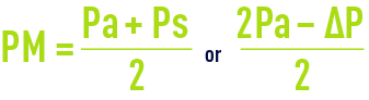
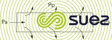
- The pressure differential across the membrane; however, pressure will vary between the module inlet and its outlet (figure 58) and internal pressure ∆P cannot be ignored in the face of pressure Pa (often limited to 0.3 maximum 1.3 bar); therefore, an average pressure is defined:


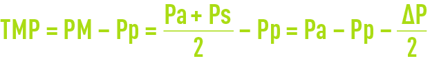
- Additionally, nor can we ignore pressure Pp through the permeate and the mean trans-membrane pressure (TMP) is defined as:
- The membrane’s permeation flow under its operating conditions is usually termed the «flow» and expressed in L · h–1·m–2 or LMH (English);
- The membrane's permeabilityor its specific or standardised flux expressed in L · h–1·m–2·bar–1 is in fact the flux the membrane would produce at a temperature of 20°C and at a 1 bar TMP. In order to make the transition from flux to permeability, we can use the type of curves found in figure 57 (linear part of the curves) in order to correct the influence of the TMP (proportionality) and then of the temperature;
We should note that a difference of 1°C at 20°C will generate a correction in the vicinity of 2.5% of permeation output and that, for example, a recorded 118 L · h–1·m–2 flux at 27°C will correspond to a 100 L· m–2·h–1 bar permeability at 20 °C, in the knowledge that this flux will be reduced to 60 L · m–2·h–1 bar should the treated water temperature fall to 2°C. Consequently, permeability is the only intrinsic value that can be used to evaluate the performance of a given membrane at a point in time t by comparing its performances with those achieved on start-up. Among other considerations, this comparison allows us to check (immediately after a backwash), the extent to which this membrane has become irreversibly fouled and, if necessary, to take the decision to either change backwash conditions or to begin a chemical clean.
fouling and backwashing
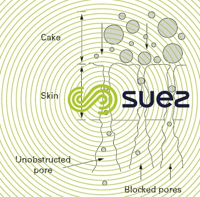
CClarification membranes that are mainly used for removing out particles tend to accumulate these particles on their surfaces in the form of a cake; this filtration cake resistance must be added to the one of the actual membrane and, in fact, tends to become preponderant compared to the membrane’s resistance; this phenomenon generates a rapid decline in permeability over time. In order to reinstate initial conditions therefore, backwashing is used to remove this cake:
- using water (UF membrane);
- using water or air.
Therefore, this backwash will consist in reversing the water flow through the membrane by pressurising the permeate side. This backwash detaches the cake that has accumulated and then pushes the debris to the outside of the hollow fibre (internal skin) and then from the module (internal or external skin). Similarly, an air backwash consists in pressurising the air in the permeate compartment in order to create bubble aeration that detaches the cake.
Hence the term reversible fouling because, once the cake has been removed, the membrane’s initial output is reinstated.
(E.g. 100 L · m–2·h–1·bar at 20 °C). Please refer to schematic diagram 90-5.
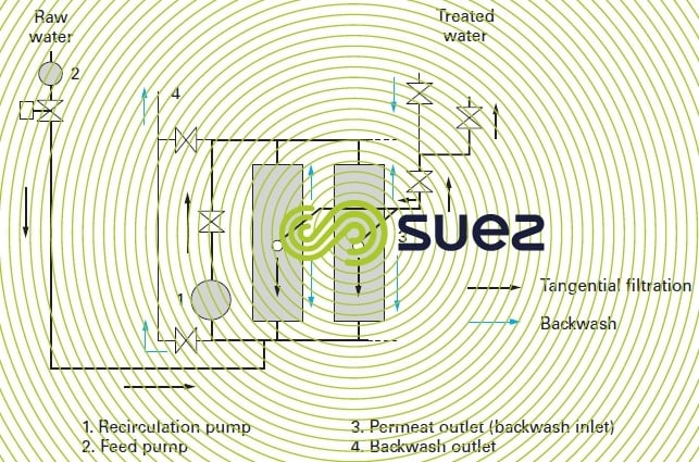
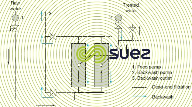
Figures 59 and 60 illustrate the most commonly used hydraulic arrangement used to carry out backwashes with the produced water.
Nevertheless, we have found as follows :
- depending on the membrane type, the more hydrophilic the membrane, the more easily the cake is detached; in fact, in this case, the cake will be separated from the membrane within the first few seconds of the backwash during which time the backwash flow repartition must be as homogeneous as possible despite the different types of fouling affecting the membrane. Even when good hydrophilic properties prevail, a higher backflow rate (often at least twice the filtration flow rate) will still be essential. The debris then has to be conveyed to the outside and this takes much longer than just dislodging the deposit: 30 to 60 s depending on the case.
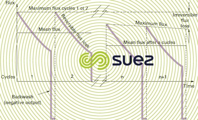
- even with membranes that have good hydrophilic properties, we will not necessarily reinstate the entire initial output and, during the cycles, irreversible fouling will gradually build up (figure 61). We then need to undertake a more effective "chemical clean".
irreversible fouling causes and mechanisms
Numerous researches have been and continue to be undertaken in order to provide a better description of and, if possible, model this fouling. It can be from at least two sources:
- pores become"mechanically" blocked(a risk that is found mainly in microfiltration). Figure 62 shows how the membrane gradually loses its flow; as some of its pores will be blocked by colloids that are of virtually the same size as the pores, it will be very likely that a backwash will clear those pores;
- organic matter adsorbed on the surface of as well as within the membrane; dissolved organic matter diffusing through the pores into the actual mass of the polymer. These adsorption risks depend significantly on the couple formed by the membrane material together with the organic matter present in the raw water and on the usual affinity between membrane and matter.
It should be noted that, matter that is easily adsorbable and able to foul almost any type of membrane will include some flocculation polymers where the residue, even at fraction of mg · L–1 levels, may be enough to generate irreversible fouling over a period of time.
utilisation : dead-end or tangential operation
WWhen the raw water is heavily loaded with suspended solids and colloids, and in order to prevent the cake from accumulating too fast, a high velocity must be maintained along the entire membrane in order to minimise the boundary layer. This is the principle of the so-called “tangential” systems where pump P1 on the recycling loop (figure 59) enables us to maintain a velocity of up to 5 m/s through tubular ceramic membranes and closer to 0.5 to 1 m/s through polymer fibre membranes. Pump P2 (the feed pump) merely maintains the trans-membrane pressure by making up the pthe permeated water volume.
This type of system can be recommended for internal skin membranes as soon as the suspended solids level in the raw water exceeds 20 mg · L–1 and becomes compulsory for maintaining an appropriate flux with water containing over 40 mg · L–1 of suspended solids. On the other hand, quite clearly, this will not change the causes and consequences of irreversible fouling.
Its main disadvantage is the amount of energy consumed by recirculation (200 to 300 W · m–3 product) at 0.6 or 0.8 m · s–1. This tangential filtration mode is no longer used in drinking water or wastewater tertiary filtration processes.
If, on the contrary, the water to be treated contains few colloids able to create a cake that is highly filtration-resistant, the dead-end system (figure 60) is simpler and less expensive both in terms of investment (no pump P1 and no recirculation loop) and operation. The only energy consumed is used to push the water through the membrane 0.1 to 0.2 kWh · m–3).
The backwash frequency is adjustable: typically 30 seconds to 1 minute every 30 to 120 minutes.
As already discussed, more intensive washes must be implemented in order to deal with "irreversible" clogging from time to time. These more intensive washes are termed chemical cleans chemical cleans. Chemical cleans involve soaking with a recirculation period in solutions appropriated to the problem encountered but usually based on the action of:
- acids and/or chelating agents: citric or oxalic acid for removing metal oxide-hydroxide deposits: Fe, Aℓ, Mn, that can penetrate the membrane to varying depths and even, typically in the case of Fe and Mn, foul the permeate side of the membrane. This particularly applies to water containing dissolved Fe or Mn (reduced forms) as these ions cross through the membrane. However, if we add an oxidising-sterilising (Cℓ2, CℓO2, H2O2) product into the water produced with a view to avoiding the membrane being recolonised by bacteria (bio fouling), this product will oxidise the Fe and Mn in their insoluble form and the oxides concerned will foul the membrane's "clean" side when it is backwashed. This type of effect can be identified through soluble Mn and Fe values <0.05 mg · L–1;
- alkaline pH detergents used to "detach" and disperse mainly organic cakes as well as possible;
- oxidant (Cℓ2, CℓO2) (when compatible with the membrane material) for "oxidising-desorbing" organic molecules that have been adsorbed on and inside the membrane and, clearly, disinfect the membrane.
All these actions take place slowly and require contact time followed by major rinsing, resulting in production downtimes of at least 4 hours and even as long as 24 hours. Therefore, these stoppages must be reduced to a minimum; the optimum would be between 1 and a maximum of 12 washes per year–1. In the meantime, it may be of value for much shorter (~1 h) "soaks" to be carried out with a citric acid solution or chlorinated water and, therefore, at much shorter intervals, (e.g. once a week) in order to delay complete chemical cleans which will, nevertheless, remain essential.

Bookmark tool
Click on the bookmark tool, highlight the last read paragraph to continue your reading later
