


chlorine
Reading time:Chlorine is the most widely used bactericide and oxidant. However, on grounds of safety, special utilisation conditions must be strictly obeyed. In addition to its use in pre-treatment, it is used for final disinfection in the following amounts :
- drinking water: approximately one mg · L–1 ;
- swimming pools: approximately 1 to 5 mg · L–1 ;
- wastewater (if required) after biological treatment: approximately ten mg · L–1 ;
- for periodic disinfection of reservoirs and drinking water distribution networks, in amounts of approximately 10 mg · L–1 with a 24-hour contact time, or 30 mg · L–1 when jet sprayed onto the walls of structures before these are filled. In this latter case, bleach is usually preferred.
materials :
Dry and cold chlorine will not attack common metals; however, it becomes highly aggressive in the presence of heat or humidity. Circuits and tanks must be kept completely dry and protected from any form of heating.
distribution and dispensing principles
For chlorine storage, please refer to current legislation and to the general information provided in sub-chapter 1 (general provisions).
Chlorine can be distributed from storage containers to the feeding unit (chlorometer) as follows:
- either as a gas for low flow rates;
- or as a liquid for higher flow rates.
When it is delivered by the chlorometer, chlorine is conveyed under negative pressure to the injector where it is dissolved in the injector water.
The resulting chlorinated water is injected at the point of use.
distribution
Calories required for the purpose of vaporisation must be provided in order to maintain a chlorine gas flow from a liquid chlorine recipient (latent vaporisation heat 56 kcal.kg-1 at 20 °C). From a practical viewpoint, a one tonne tank of chlorine can deliver (without an external injection of heat) approximately 10 kg of chlorine per hour in premises where the temperature is kept to 20°C. For higher flow rates, heat has to be provided by an evaporator (vat with a thermostatically controlled temperature of approximately 80°C). Chlorine is then extracted from tanks in liquid and not in gaseous phase.
feeding
Chlorine gas delivered either directly from tanks or cylinders or from evaporators, is measured and expanded to service pressure in a unit called a chlorometer.
The vacuum chlorometer principle is based on changes in chlorine output controlled by modulating a vacuum created by an injector where the chlorine gas is dissolved in the injector water.
chlorine feeding units operating in a vacuum
The vacuum device technique was developed with a twofold purpose of ensuring that chlorine distribution is automatically switched off when no dissolution water is available, and to prevent chlorine from being discharged to the atmosphere in the event of a leak.
The vacuum is created by an injector that is also used to dissolve the chlorine in water.
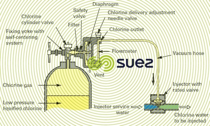
compact chlorometer
This type of unit is particularly well suited to low chlorine flow rates and can be fitted direct onto the chlorine cylinder head; it is occasionally coupled to the cylinder head by a short hose.
Connections must always be as short as possible, thereby avoiding the danger of leaks; however, when the chlorometer is mounted direct onto the cylinder, precautions are required when handling the connection because it then has to be removed each time a cylinder is replaced.
The principle applicable to this device can be seen in figure 14. As the pressurised injector water travels through the injector, it creates a vacuum in the pipeline between the flowmeter and the injector. This vacuum opens the chlorometer’s safety valve. Chlorine is drawn into the chlorometer, through the flowmeter’s graduated tube and then through the flow regulating needle valve. When it reaches the injector, it is instantly dissolved in the injector water and forms a chlorinated solution. In the event of an accidental break or a leak affecting the pipe between the injector and the dispenser, the vacuum is broken at the diaphragm, causing the chlorine feed safety valve to close.

The most widely used models provide the following options:
- the possibility of automatically switching from one chlorine cylinder to another when one cylinder is empty;
- "bottle empty" or "no chlorine" indications.
(Refer also to figure 15 for a separate compact chlorometer).
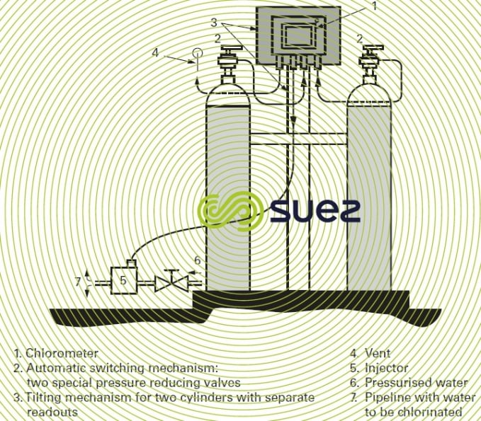
This type of "compact" chlorometer can be fitted direct onto chlorine cylinders and tanks and is appropriate to amounts of between 5 and 4,000 g · h–1 of Cℓ2.
high flow rate chlorometers
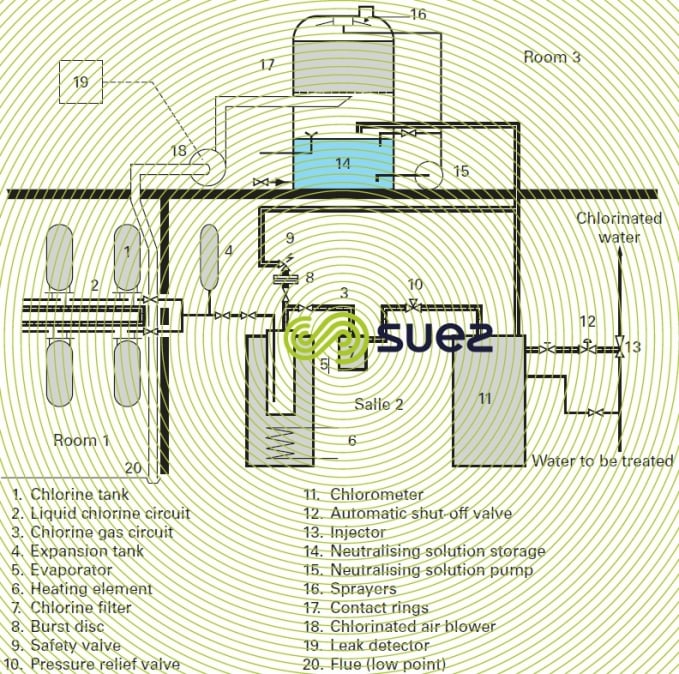
High flow rate chlorometers operate in the same way as those described above, under a modulated vacuum, fed from a chlorine tank. Their capacity can reach 200 kg · h–1 (which is the maximum capacity of an evaporator). Figure 16 shows a complete dispensing unit that uses this type of chlorometer.
detecting and neutralising chlorine leaks
Chlorine gas is greenish yellow in colour and has an irritating smell. Two and a half times heavier than air, it will stagnate at ground level in the event of a leak.
In the case of storage facilities of a certain size, French legislation imposes the installation, in separate premises (see upper section of figure 16), of a chlorine leak detector and of an arrangement used to neutralise these leaks.
The neutralisation premises comprise:
- a blower (18) for the chlorinated air to be neutralised;
- a neutralisation column with packing (17);
- a storage tank (14) holding the neutralising solution, the pump (15) used to spray the packing as soon as a leak has been detected;
- the leak detector (19).
The leak detector and chlorinated air blower (18) suction systems are positioned near the floor of the storage premises.
The neutralisation solution usually consists of sodium hydroxide and sodium hyposulphite. Sodium hydroxide is used to absorb chlorine and convert it into reduced hypochlorite and then into Cℓ– by the hyposulphite.
The sodium hydroxide also neutralises the acidity released by the action of chlorine on the hyposulphite.
Approximately 1.1 kg of hyposulphite and 1.7 kg of sodium hydroxide are required to neutralise 1 kg of chlorine.
diagram of a complete system
Figure 16 shows a system comprising the storage, liquid phase extraction, evaporation (5) and then the feeding in gas phase ( 11 and 13), and leak neutralisation (14 to 19).

Bookmark tool
Click on the bookmark tool, highlight the last read paragraph to continue your reading later
