


treating make-up water
Reading time:The section boiler water, provides examples of the quality demanded for boiler feed water (extract from draft European standards). In order to meet these requirements, supplementary water treatment will almost always be necessary and, depending on the quality of the raw water, will often start with clarification filtration used to produce water having physical properties that are compatible with treatments over resin and/or membrane that are essential for guaranteeing the requisite chemical quality. Additionally, Using ion exchangers and Separation by membranes describe the various technologies applied, involving ion exchange and/or membranes, even electro-deionizers, elements that are absolutely essential in make-up water treatments.
low and medium pressure boiler carbonate removal and softening units
Minimum treatment usually consists in softening designed to obtain a TH that is as close to zero as possible.
At low pressures, softening is used on its own whereas at intermediate pressures, carbonate removal, silica removal may be combined with softening if necessary, using a range of different methods. The main methods used are :
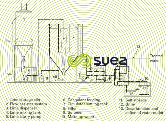
- carbonate removal using lime, from cold, with optionalsilica removalusing magnesium oxide or chloride or aluminate followed by softening (seeremoving hardness (calcium and magnesium)) ;
- carbonate removal using lime with silica removal using magnesium oxide, from hot (95 to 110°C) followed by softening (rarely used nowadays) ;
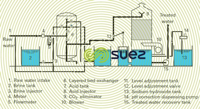
- carbonate removal through a carboxylic cation exchanger (see classic schemes used) followed by softening and including physical removal of CO2 by stripping (far less expensive than fixing it on a strong anionic resin).
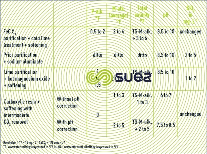
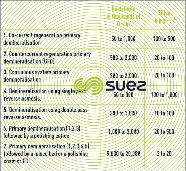
As an aid to selecting the appropriate system, table 1 provides the results expected of each.
After these treatments, it is advisable to undertake the physical (de-aeration) or chemical removal of oxygen and conditioning.
Figures 1 and 2 provide examples of installations.

total demineralization lines (medium and high pressure boilers)
When the above processes do not provide the necessary quality, make-up water will have to undergo total demineralization using ion exchange and/or reverse osmosis.
Depending on the composition of the make-up water, boiler type and pressure, we will need to use one of the systems described in table 2.
If, for minimum TAC levels, the requisite :


ratio is not obtained, the necessary corrections will have to be made in order to reinstate a suitable boiler water silica / alkalinity ratio.
All these figures are provided for guidance. They transcend the range when starting with heavily mineralized water, polluted water or water that has undergone inadequate pre-treatment.
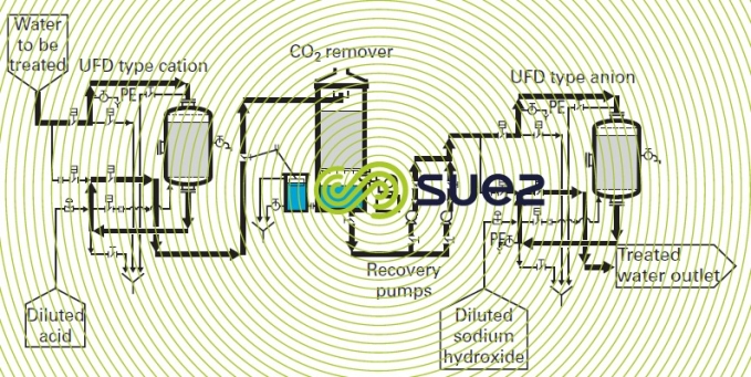
The scheme in figure 3 shows an installation comprising a very acid cation exchanger and a very alkaline anion exchanger with CO2 remover. This is the simplest scheme for a demineralization line.
For HP boiler feeds, a total demineralization type installation can include :
- a pre-treatment : clarification or carbonate removal followed by filtration ;
- a primary line of ion exchangers where the following are compulsory :
- either a strong cation ( CF ) and a strong anion (AF) and possibly a weak cation (Cf) and a weak anion (Af) where CO2 is often eliminated between cationic and anionic exchangers ;
- or single or double pass reverse osmosis.
This type of system should produce water having a resistivity of more than 50 KΩ·cm, free of turbidity < 0.1 NTU) or organic matter (TOC < 0.5 mg · L–1) :
- a secondary line comprising either a CF and an AF, or a mixed bed (LM), either a single polishing cation or electro-deionization (see Separation by membranes),
At this stage, water having a resistivity better than 5 MΩ/cm will be obtained.
- chemical conditioning.
The scheme illustrated by figure 4 represents a total demineralization line for a nuclear power station comprising a primary cation-anion line with countercurrent regeneration and a polishing mixed bed.
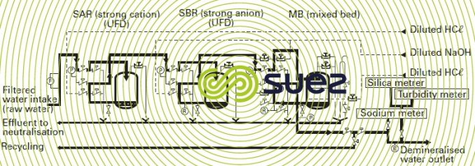
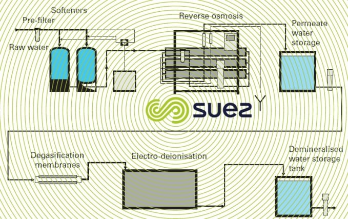
Another example of a treatment that uses more advanced technologies is shown in figure 5. It should be noted that, apart from the softener’s regeneration salt, the other units no longer use physical processes thus discharging minimum amounts of salt into the environment.
de-aeration units
For oxygen removal from make-up water, de-aerating can be carried out using physical means such as vacuum de-aerators, thermal de-aerators (see air or gas strippers, removing CO2 and thermal de-aerators), or de-aeration membranes (see permeation processes), or alternately using chemical means such as oxygen reducers (usually at the polishing stage) or catalytic resins (see main types of ion exchangers).
Carbon dioxide is always removed using the physical method (air stripping).
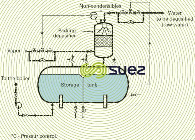
Thermal de-aerators (or vapour stripping) are the most widely used; as a rule, their operating temperature will vary between 105°C and 140°C and tank capacity has to be calculated for 15 to 60 minutes of storage at nominal flow rates.
Oxygen-free condensates are routed direct to the storage tank while condensates containing O2 pollution have to be de-aerated using make-up water (figure 6).
Bookmark tool
Click on the bookmark tool, highlight the last read paragraph to continue your reading later
