


mechanical blocking
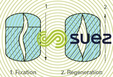
Reading time:Various methods may be used to ensure mechanical resin blocking, such as inflating a diaphragm during regeneration (figure 3), filling the empty space above the resin bed with an inert material, etc. Practically, the most commonly used method consists in placing the resin layer between two mechanisms (e.g. nozzle plates), which enables the regenerant to be injected and the eluate to be discharged, while preventing the resin bed from expanding; practically no space is left above the resin bed.
All of these processes require an additional column into which all or part of the resin must be transferred from time to time in order to remove the resin fines that are created and/or the suspended solids introduced by raw water and reagents.
They can be classified in one of two categories, depending on whether percolation during the production cycle flows upward or downward.

upflow production cycle processes
« floting beds »
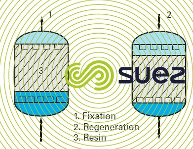
The production cycle operates from bottom to top, and regeneration from top to bottom (figure 4).
In a production mode, due to the speed of passage, the uppermost part of the resin bed is compacted against the drainage system, while the lower section may be partially in suspension. This layer takes up the majority of the ions and operates under total saturation, whereas the upper section, better regenerated, is used as a polishing layer for assuring quality. A layer of inert resin protects the nozzles in the top plate.
The inherent disadvantage of this system is the inability to stop and significantly reduce the flow in mid-cycle, due to the risk of disrupting the resin bed layers.
Variations of this system are proposed in order to overcome the above disadvantage, in particular to remove the washing column.
other processes
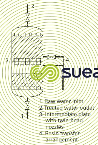
In the Liftbett process, the ion exchanger unit is divided into two superimposed chambers, separated by a plate (3) fitted with twin head nozzles (figure 5).
The upper compartment is completely filled with resin, whereas the lower compartment is empty, thus allowing the bed in this part to be backwashed. The two compartments are interconnected by a device (4), designed for the hydraulic transfer of the resins. This system frees the upper chamber for backwashing, in which case some of the resin is simply transferred to the lower chamber. Once backwashing has been completed, this resin is transferred back into the upper chamber. This arrangement allows the production process to be interrupted at any given moment without adversely affecting the quality of water once operation is resumed. Indeed, the polishing layer in the upper chamber remains compact andcannot mix into the saturated resin.
Amberpack is a compacted bed process similar to the floating bed system with an external washing column but without inert resin.
downflow production cycle process
As opposed to floating beds, in the UFD (up flow Degrémont®), the production cycle takes place in downflow, and regeneration in upflow.
Similarly, unlike floating beds, the water produced is free of fine resin particles and suspended matter.
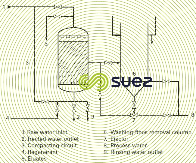
The UFD consists of a column with two liquid distribution and/or collection systems (usually nozzle plates or, less frequently, branched collectors) divided by a resin bed occupying about 95% of the space between the two systems (figure 6).
In operation, a preliminary “compacting” sequence is obtained during regeneration to block the resin bed; this process consists in subjecting the resin bed to a strong up-flow stream of water; due to the high velocity and the limited space, the resin bed rises like a piston, becoming blocked against the upper collection system, and so unable to expand and there is therefore no risk of the layers being mixed. Moreover, when the compacting flow is maintained for just a few minutes, a highly compacted resin layer can be obtained, which then enables injection of reagents at much lower velocities, without the resin bed dropping and disintegrating.
The fact that the production cycle takes place from top to bottom makes the UFD insensitive to flow fluctuations and mid-cycle interruptions. Because this is a downflow production cycle, the UFD is impervious to flow rate fluctuations and to mid-cycle interruptions. Moreover, if there are suspended solids in the water, they are stopped by the upper layer of the resin bed, and will be mostly removed during the subsequent regeneration compacting sequence.
Similarly, fine resin particles are evacuated during this compacting sequence.
The upper layer or the entire resin bed can be transferred hydraulically to a washing column where it is washed with water, and then hydraulically returned to the exchanger; this is also carried out hydraulically. The frequency of this operation depends on the increase in head loss during the production cycle. With clean water, one bed decompaction and washing operation per year may suffice.
use of superimposed beds
It is possible to combine in a single production unit both strong and weak ion exchangers of equal polarity, separated by an intermediate nozzle plate. During the fixing cycle, the liquid being treated successively percolates through the weak resin first and then through the strong resin, whereas the opposite applies to the reagent, when it goes through the regeneration phase. This would allow the «strong base» resin to be regenerated with a high excess of reagent; the excess is calculated based on the quantity required to regenerate the weak base resin. For the record, the use of “weak” resins in superimposed beds or separated beds permits rates of between 105 and 115% of stoichiometry to be reached for resin regeneration. “Strong” resins require much higher regeneration rates.
Due to its simplicity, the UFD is perfectly adapted to the practical applications of superimposed beds.
performance of exchangers regenerated by countercurrent methods
Regeneration by countercurrent methods produces much higher quality water than regeneration by cocurrent. With water of moderate salinity and silica contents, conductivity at the outlet of the primary treatment line is generally between 0.5 and 5 µS · cm–1 and the silica content is usually less than 50 µg · L–1. Through countercurrent regeneration, it is often possible to avoid the use of a polishing line for MP boiler feedwater and some of the process waters.
Another advantage: the countercurrent regeneration method permits the volume of service water necessary for regeneration to be considerably reduced.
Bookmark tool
Click on the bookmark tool, highlight the last read paragraph to continue your reading later
