


changes in limitations applicable to control-regulation systems
Reading time:The water treatment industry is governed by two major restrictions:
- increasingly stringent standards and, therefore, processes that are becoming more and more complex;
- clients, local authorities, industry or private individuals who want to see the price of water being controlled (investment and running costs).
This means that, in the cases where plants are designed to operate close to their limits, there is little room to manoeuvre between the standard that constantly applies and the capability of the process that has been installed. Therefore, the plant must be properly operated. Consequently, this means that any discrepancy or malfunction must be detected immediately so that either the set points, or equipment operation, or….. can be rectified or adjusted in real-time.
Furthermore, the operator must organise matters so that he optimises his resources and keep a flexible staff: operating units, undertaking first level maintenance … and no longer waiting around in a control centre. Information, alarms, overview of the plant or unit status must reach operators wherever they are.
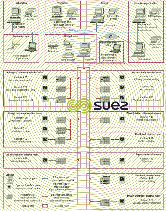
For a good understanding of the following, please refer to the glossary provided below:
- redundant programmable logic controller: two types of redundant programmable logic controllers are used, each comprising two CPUs and software redundancy in the same programmable logic controller. They are termed: Warm stand-by or Hot stand-by. For instance, on Hot stand by, the system operates on the master-slave immediate response principle: the same program is loaded into both CPUs and runs as soon as common input data is acquired, both CPUs being perfectly synchronised. All data blocks are shared between the two CPUs, but one of the two sub-systems is the process master and responsible for updating output. As soon as a fault appears, the standby unit, having fully updated data, immediately takes control. This solution produces CPU assembly, supply and network card reliability levels that are better than 10 years;
- SCC [=système de contrôle-commande in French]: control and regulation system;
- IHM [=interface homme-machine in French]: man-machine interface;
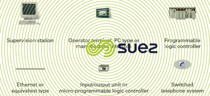
- please refer to figure 2 for the icons used in the SCC architecture diagrams.

The following provides eight examples of the architecture recommended by SUEZ for drinking water, wastewater or sludge treatment units.
drinking water plant
Until recently, plants primarily focused on:
- sedimentation/filtration systems (sand or carbon) that only rarely (approximately once a week) required any changes to their process parameters (at least, in areas that were normally stable);
- sequential filter management, especially covering cycles of 24 hours or longer (approximately 30-minute washing time).
Today, plants have moved over to systems that use clarification membranes that have a 20 to 60 minutes cycle between backwashes (each backwash lasting approximately one minute) calling for:
- pressure and flow adjustments several times per cycle (or else the flow declines as fouling builds up);
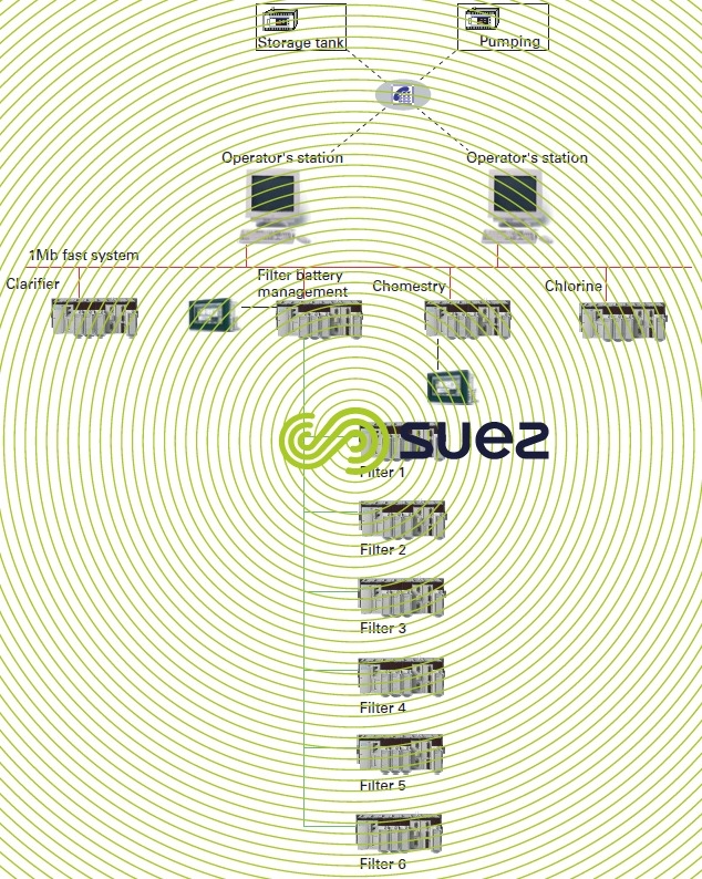
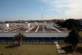
- a large number of blocks (some fifty in Moscow – figure 4) that regularly become unavailable through the periodic need for thorough backwashing or even chemical rinses.
These developments have been reflected in the two architecture illustrations described below.
classic solution architecture (see Johore Bahru example, figure 3)
This plant is already heavily automated, comprising of automatically controlled Aquazur filter adjustment and filter battery management. The new technologies offered, Pulsator clarifiers and filters, allow the operator to run his plant manually in a crippled mode.
Some operations do benefit from simple automated controls in order to facilitate the operator’s tasks, e.g. using the raw water flow rate to control pH or coagulation-flocculation reagents.
Filter washing is fully automated and the following priorities will initiate filter washes: maximum filter fouling, cycle duration, hand operator.
The drinking water plant is, therefore, often the place where the operator monitors the entire system, including its pumping stations. Consequently, it is connected to telesurveillance systems via a switched telephone network.
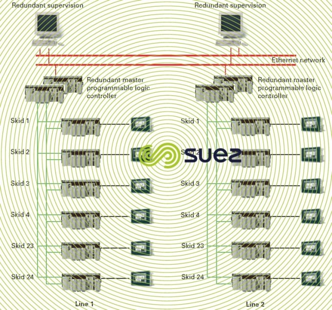
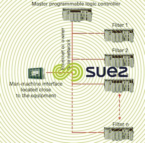
membrane solution architecture (see UF architecture e.g. Moscow, figure 4)
The architecture of ultrafiltration plants using Aquasource® blocks with Ultrazurs follows the plant’s functional breakdown. For each ultrafiltration block (48 in all), SUEZ has included a programmable logic controller and a man-machine interface (IHM). This solution allows equipment mounted on the skid to be commanded via the programmable logic controller, when maintenance operations are being carried out. Manually controlled operations outside the programmable logic controller are prohibited as they could result in membrane damage.
Without the programmable logic controller, the operator would be unable to run the skid or the plant.
The master programmable logic controller responsible for skid management, also co-ordinates the whole: feed, wash authorisation… It plays a crucial role and the installation of a Warm stand-by or Hot stand-by redundant programmable logic controller solution is essential (please refer to the definition of a redundant programmable logic controller).
In this type of plant, the operator no longer sees the water as it progresses through the treatment system. Therefore, it is absolutely essential that he has access to real time data in order to run the plant. Consequently, he needs a reliable and sturdy control-regulation system [SCC]. In order to secure this aspect, SUEZ has developed, alongside an approach intended to standardise these skids, standardisation of the software used with skid and master programmable logic controllers.
This approach has led to reduced construction costs while providing the operator with an industrially proven and reliable tool. This approach has also produced more functionality for the operator than software that would have been developed specifically for the plant in question.
This standardisation is based on a functional breakdown illustrated by figure 5.
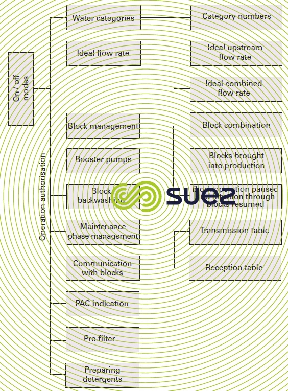
Therefore, the software is broken down into elementary process sub-functions. As in IT applications, this allows us to produce simpler and better defined functions. Operating instructions and a functional analysis are produced for each function. Each function is tested individually and then as it interacts with all the other functions. This approach enables us to produce programmable logic controller and supervision software without being affected by delivery limitations imposed by contracts and to do so in a more meticulous manner.
In the case of each function shown in the diagram by a rectangle, SUEZ has developed a function block as defined by the IEC 1131-3 standard. Once this development had been completed, SUEZ was able to configure, and no longer to program, these elementary functions. This elementary function configuration is undertaken according to plant operating modes (e.g. dead-end or tangential) and to process criteria and no longer on the basis of criteria specific to automated control specialists.
This structured approach calls for an exchange between automated control specialists and experts, the breakdown emerging from a function-by-function analysis of the process. We no longer refer to programmable logic controller tasks and even less to words, bits….
The result is a standard program for the block programmable logic controller that ‘talks’ to the master programmable logic controller. Thus, for each individual project, we can incorporate any improvement made to the process or its controlregulation system and achieve increasingly reliable programmable logic controller software.
watstewater
We have moved on from high retention time (24 hours for low loading, 6 hours for high loading) activated sludge residence time plants where reactions tend to be based on sludge age (1 to 10 days), to systems based on biofilters that fulfil a number of purposes (C, N, DN…) and, therefore, to different processes, to cycles that vary from 10 to 48 hours but, above all, that require a great many operations during that cycle in order to adjust process parameters such as the number of filters needed, aeration rate... to the instant pollution flow rates to be processed (actual water retention time in the biofilter being limited to 5-15 minutes).
activated sludge plant architecture
With this type of plant, the control-regulation system manages a few operating sequences and, more importantly, warns the operator in the event of a malfunction, either in the control centre (supervision), or on standby duty.
The operator can always run his equipment manually. There is no danger that the process will be affected or that the equipment will be damaged: because processes can cope with a shutdown lasting a few hours and when equipment is started up or shut down, this is little effect on the plant’s operation.
Problems will arise in connection with the maintenance of either a cabinet/programmable logic controller, or of a man-machine interface because when this type of equipment is shut down, it must not affect the satisfactory operation of several units/structures. Therefore, programmable logic controller and man-machine interfaces must be disposed according to unit/structure and not to geographical location in order to reduce wiring. This is illustrated by the architecture used at the Tours (France) plant (figure 6) where the most sophisticated functions tend to involve SCC exchanges with supervision – computer assisted maintenance [MAO in French] – laboratory systems.
compact plants based on biofilters
These plants that often comprise elaborate sludge processing (drying, incineration …) and biofilters can usually be found in urban or sensitive locations. Problems they create for the environment must, therefore, be strictly limited. Additionally, these plants are more often than not covered over, ventilated and subject to odour control. If the ventilation system stops, this can gradually induce H2S levels higher than those allowing operators to work in these areas. Therefore, any work required must be carried out with all due haste.
These plants are designed to operate with variable pollution levels or throughputs and the control-regulation system occasionally has to switch the unit from one configuration (for instance with filters in series 2 by 2 or 3 by 3) to a different configuration (where all the filters are operating in parallel) to ensure that the plant can cope with an extremely high hydraulic overload. Therefore, the management sequences applicable to these biofilters are very complex, especially in view of the number of variables to be processed.
There are three possible architectures for this type of plant:
- either a programmable logic controller for each filter and one non-redundant programmable logic controller responsible for managing the man-machine interfaces on the dead-end programmable logic controller and close to the main items of equipment (see Biofor architecture solution 1 figure 7) "all in parallel";
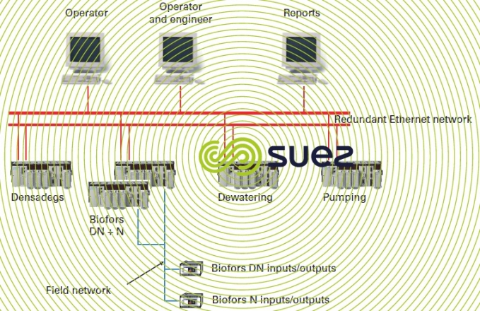
- or a redundant programmable logic controller with remote inputs/outputs and man-machine interfaces distributed throughout the plant (see Biofor architecture solution 2 – figure 8);
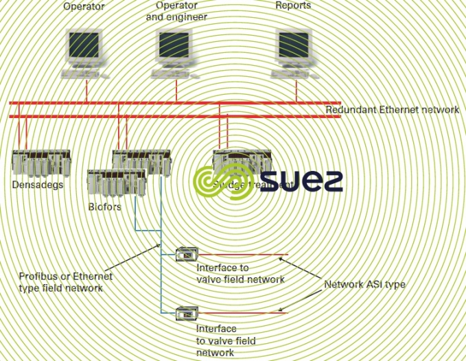
- or a redundant programmable logic controller with valves directly connected to a field network and man-machine interfaces distributed throughout the plant (see solution 3 – figure 9).
Advantages of the first solution:
- each filter operates independently;
- the master programmable logic controller only manages priority signals and the number of filters in service;
- it is easy to use and maintain.
This solution has the following drawbacks:
- should the master programmable logic controller fail, the operator can no longer manage his battery (initiating a wash, calculating the number of filters based on throughput or pollution… );
- many programmable logic controllers are installed and maintenance is expensive.
Advantages of the second solution:
- sturdy and reliable solution;
- simplified wiring between valves and the programmable logic controller.
This second solution has the following drawbacks:
- expensive to implement;
- complicated master programmable logic controller software.
Advantages of the third solution:
- reliable solution;
- wiring simplified by using the site network.
This third solution only has one drawback: the operators need to have control of the site networks.
Each case has to be decided on merit. Nevertheless, we tend to recommend the second or third solution.
sludge treatment
Processes also move from mechanical dewatering systems where there are few available control parameters to thermal processes where the process itself, or the system safeguarding men and equipment requires reaction times of less than one millisecond. The stringent nature of flue gas discharge standards requires systems to operate at their design limits and the need for Control-Regulation systems that rapidly detect any discrepancy.
"classic" solution architecture (example of a centrifugation unit)
Modern centrifuges require a man-machine interface for ease of testing and adjustment. However, overriding controls will be restricted to start/stop and washing sequences. The machine itself, without a programmable logic controller but with a specific controller, performs the dewatering function (differential speed adjustment, see high pressure centrifuges).
architecture applicable to thermal processes
Thermal processes, furnace and dryer are instument laden. Some dryers require programmable logic controller programs with rapid emergency shutdown sequences including procedures to avoid any fires starting up. Therefore the programmable logic controller programs are complicated and difficult to use. With a view to making these programmable logic controller programs reliable, SUEZ has developed, in the same way as had been done for ultrafiltration, certain specific modules. However, thermal processes are too variable to be entirely standardised. Therefore, we shall restrict ourselves to defining a few function blocks, the remainder of the program being designed specifically for each individual project.
Bookmark tool
Click on the bookmark tool, highlight the last read paragraph to continue your reading later
