


treatability tests
Reading time:oxygen consumption measurements: respirometry
As previously discussed (Fundamental biological engineering processes applicable to water treatment), monitoring the oxygen consumption from an aerobic biomass is one of the preferred methods to ascertain either the biodegradability/toxicity of an effluent ( BOD ) or the condition of an existing biomass and its potential in relation to a given effluent ( BOD or specific pollution components removal kinetics).
manometric measurement : Warburg respirometry
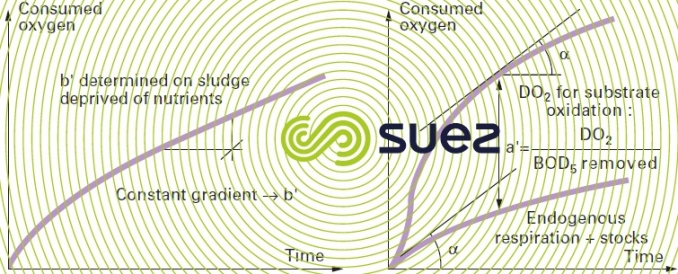
The Warburg respirometer is not so much a control apparatus but rather a manometric equipment that is used to study the respiratory action of activated sludge, using a small volume sample (a few mL) depending on the oxygen concentration.
The respirometer can be used to determine the respiratory coefficients a', b' of an activated sludge (see chap. 4) as illustrated by figure 14.

Very delicate to operate, Warburg respirometers are actually no longer used. These respirometers have now been replaced by systems such as the one shown in figure 15, which are used to carry out a direct and continuous measurement of the oxygen consumption rate in a closed biological reactor.
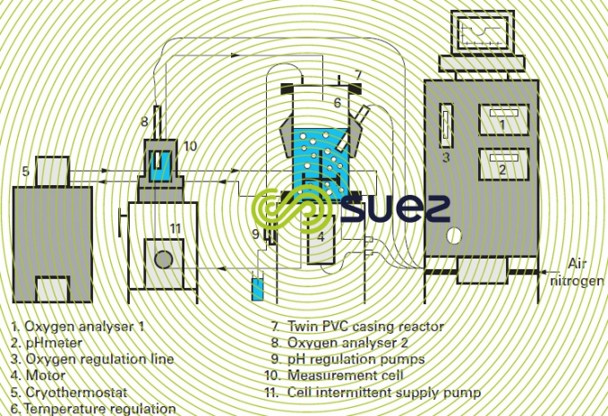
In measurement cell 10 (figure 15), in the absence of any incoming air the dissolved oxygen concentration decreases linearly and in proportion to the microorganism activity (figure 16).
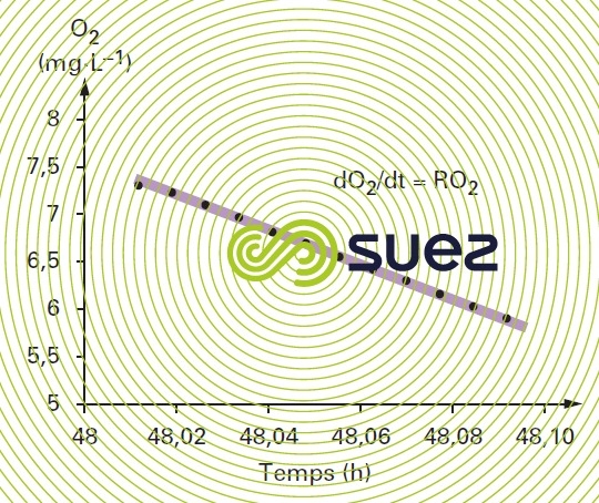
Measuring the reactor biomass concentration enables to establish the amount of oxygen consumed at the temperature set by the thermostat; g O2 per g VS per h.
This respirometer can be used to:
- measure an effluent toxicity (intermittently in order to establish a toxicity threshold or in-line when acting as an alarm to detect an abnormally low RO2);
- identify an effluent biodegradability (rapidly degradable fraction, slowly degradable fraction, non biodegradable fraction);
- measure respiratory coefficients.
nitrification test
An effluent seeded with nitrifying sludge or specific strains is aerated and agitated in a flask. The NO3, NO2 and NH4 forms of nitrogen are checked at regular intervals. The curves showing the development of nitrogen species are used to assess treatability and oxidation kinetics. These tests are mainly applied to WW when the presence of an inhibitor is suspected.
denitrification test
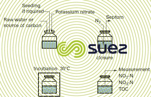
This qualitative test is used to evaluate denitrification kinetics in either an industrial WW or in a nitrified municipal WW with or without the addition of a carbon source (e.g. methanol).
Figure 17 illustrates the test procedure. The flasks used are sealed off with a septum that enables injection and sample extraction using a syringe to avoid altering the medium anoxic (a preliminary nitrogen sweep is required).
bench test
aerobic medium
Continuous or batch (small SBR ) reactors are used with in most cases an injection of air in excess. Global intake and discharge COD and BOD are monitored with time. pH, redox potential, oxygen concentration, TOC , suspended solids and volatile suspended solids can be continuously checked within the reactor.
Figure 18 displays a laboratory apparatus that simulates an actual small waste- water treatment plant with aeration and clarification zones. After aeration the activated sludge is sent to the bottom section of a clarification cylinder and recycled by an “emulsifier” after being separated from the treated water. This is a complete mixed system, which simplifies the mathematical equations that can be used to describe the system performance as a function of the operating parameters.
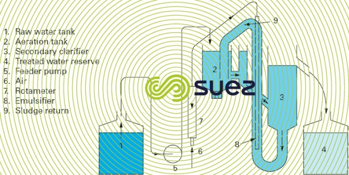
The emulsifier can be replaced by a peristaltic pump to precisely regulate the recycling flow rate and to separate aeration from the return sludge pumping.
In order to acclimate activated sludge to a difficult industrial WW, sludge taken from a municipal wastewater treatment plant is used as a seed. The pilot unit is fed with a mixture of municipal wastewater and water to be tested. Within approximately ten days, the proportion of industrial WW is gradually increased by stage of one or two days. If the proportion of industrial WW reaches 100% of the total feed without any noticeable upset the waste effluent is deemed suitable for direct biological treatment. Otherwise, the higher portion of the industrial WW reached is noted to establish the proper dilution rate within a municipal WW with the goal to ensure that the feed mixture remains a viable substrate for microorganisms. Obviously, this test has to be carried out on a medium that is balanced, whether naturally or artificially, in terms of assimilable carbon, nitrogen and phosphorus.
anaerobic medium
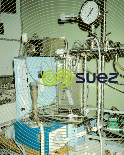
Intermittent fermentations are carried out in small reactors (photo 6) seeded using an anaerobically digested sludge obtained from a digester located in a municipal WWTP that treats sewage effluents obtained from a wide diversity of population. Initial operations are carried out under nitrogen bubble aeration in sealed flasks that are maintained at 37°C using strirred and heated water baths. Gas and reactor effluent samples are collected at regular intervals to check on methane production and COD removal.
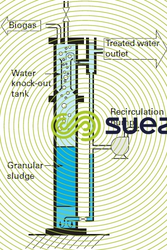
Attached growth, hybrid growth or granular sludge bed reactors (figure 19) with continuous feed can also be used.
Controls on gas production rate and composition are performed regularly. Parameters such as, pH , temperature, VFA , M-alk., COD … are measured on both the feed and reactor content.
This extensive monitoring enables the determination of the biodegradable fraction of waste effluents; information on degradation kinetics, inhibition phenomena and toxicity can also be obtained.
(Note: a 3-4 month study is often required in view of the length of the sludge latency and acclimation phases).
Bookmark tool
Click on the bookmark tool, highlight the last read paragraph to continue your reading later
