


declining rate filters
Reading time:Some gravity filter batteries can operate with a variable flow rate, without individual control and without significant level changes (figure 23).
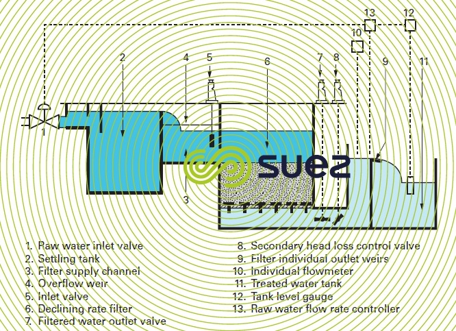

In this case, filters are supplied with settled water from the same pipeline or the same channel, without a fall, since no distribution is required.
The filtered water flows into individual basins where the weir (9) is set so that the filter bed remains covered when the filters are shut down or only operate at a low flow rate. Each filter outlet is equipped with a shut-off valve (7), backed up by a valve (8) that creates an additional head loss. The raw water feed (1) is adjusted according to the level in the treated water tank (11) by means of a level sensor (12) and a general controller (13).
In this type of scheme, the secondary head loss p generated by valve (8) is adjusted so that for the maximum flow rate Q processed by the plant :
- the individual output from the filters will vary according to their level of fouling by ± m % of the average value of the Q/N output, N being the number of filters in service. Consequently, after being washed, a clean filter will deliver: (1 + m/100) × Q/N and, before being washed, a fouled filter will deliver: (1 –m/100) × Q/N. At present the usual values attributed to m vary from 20 to 30% depending on the maximum rate through clean sand:
- the head loss suffered by the filter before it is washed must be such that, when reduced to its value for an average filtration rate, it reaches the customary values of 1.75 to 2 metres.
These two conditions set both the secondary head loss p and the geometric drop that can be expected through the filters.
According to the diagram in figure 26, the raw water flow rate is modulated according to the level in the tank and this generates a variable level over the filters. The operation of declining rate filters requires a knowledge of the individual output of each filter; this output can be measured applying the same scheme, using the water height at the weir (9) or a head loss through a narrowed section (valve …).
This type of filter control produces :
- a considerable water head over the filter bed;
- higher filter and civil engineering structure than that applicable to a filter operating at the same average rate;
- an inferior quality of filtered water at the start of the cycle due to the high initial rate;
- prolonged isolation of a filter undergoing a wash. In effect, the first step consists in emptying out, by filtration, a large volume of water from above the filter bed; the filter then has to be washed and gradually brought back into service and this can all take up to one hour per filter. This can result in an extra filter compared with conventionally controlled systems;
- relatively easy operation when the general throughput and the quality of the water to be filtered remain constant;
- on the other hand, its operation becomes more problematic when :
- the general throughput to be treated by a plant varies: in this case, each time the general throughput varies, the additional head loss generated by valve (8) has to be adjusted;
- the quality of the water to be filtered degenerates suddenly; in this case, the level in the clarified water launder rises fast. This creates major risks of discharging through the overflow (4).
Bookmark tool
Click on the bookmark tool, highlight the last read paragraph to continue your reading later
