


constant rate compensated-clogging filter - video
Reading time:At the same time, the aim is to ensure that the water level over the filters remains fixed or only fluctuates slightly and that the filtered water delivered 2 to 3 metres lower maintains a flow rate that is constant and equal to the total incoming flow rate, divided by the number of filters.
A filter rate controller mounted on each filter’s outlet, maintains a constant flow rate, regardless of the filter’s level of fouling, whether this filter rate controller is a flow rate controller or a level controller; the system includes an equal distribution mechanism. This device generates a secondary head loss that becomes significant when the filter is clean and which is cancelled out when the filter is completely fouled; in this way, the filter rate controller compensates for filter bed fouling.
Compared with constant rate variable head filters, constant rate compensated-clogging filters have the advantage of a stable treated water quality and of reliable operation, even in cases involving sudden flow rates fluctuation .
filter battery control
In general, two types of control are used: control with flow rate measurement and control in association with the maintenance of a constant level.
control with flow rate measurement
Each filter is equipped with a flowmeter and with a flow regulation device (butterfly valve, air plug valve, siphon) installed on the filtered water outlet. A filter rate controller receives a signal from the flowmeter and actuates the regulating unit which adjusts the output to a set point value.
The inevitable discrepancies between the sum of filter set point flow rates and the overall flow rate applicable to battery will be seen as changes in the water level over the filters. Therefore, additional control will be required to adjust this level by altering individual flow rate set points based on the level measured upstream from the battery (when the flow rate imposed is the incoming flow rate) supplemented by a downstream level measurement (when the flow rate imposed is the outlet flow rate).
In both cases, changes in water sheet level in the channel and in the filters can be as high as 30 cm.
control with constant level maintenance
A constant flow rate can also be obtained from each filter through constant level. In this case, start by evenly distributing the entire flow between the filters whose outlet unit is controlled by the upstream or, if necessary, downstream constant level measurement used as a reference.
Using upstream control (figure 19), the flow entering into the plant is first evenly distributed to the inlet of each filter which thus receives a flow rate equal to the incoming flow rate divided by the number of filters.

Each filter is equipped with a filter rate controller unit that detects the upstream level that it keeps constant by acting on the outlet flow rate adjustment unit. Because the upstream level is kept constant, the outlet flow rate will be equal to the incoming flow rate, compensating for fouling.
In this constant level control mode, an evenly distributed flow is achieved easily and reliably using static mechanisms (diaphragms, weirs). This mode avoids discrepancies that could occur between the total filtered flow rate and the incoming flow rate that happen with control systems that use a flow rate measurement. It is on these grounds that we prefer this type of control. Additionally, when a filter is shut down, the incoming flow is automatically distributed over the filters remaining in service.
filter rate controllers
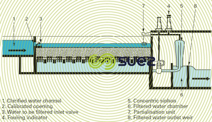
level control using siphons
The Degrémont® concentric siphon and its partialisation unit (figure 20) are used for level control. The partialisation unit constitutes a measuring and control unit and the siphon is a control unit.
siphon
This unit consists of two concentric tubes. Flow goes from the inner branch to the outer branch.
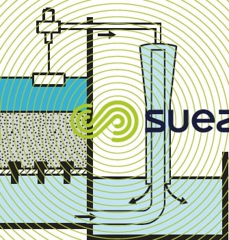
When air is injected into the top, it is drawn by the water into the downstream branch where the air-water mixture density is lowered, this reducing the vacuum in the neck. Without partialization air, the vacuum at the neck is equal, to within the pressure drop in the downstream branch, to the height “H” which is the difference between the filtered water level and the downstream filtered water chamber level. With air partialisation, this void is reduced to height " h1 ", equal to the product of “H” by the waterair mix density. The difference H – h1 = h2 represents the pressure drop thus created by the air input (figure 21).
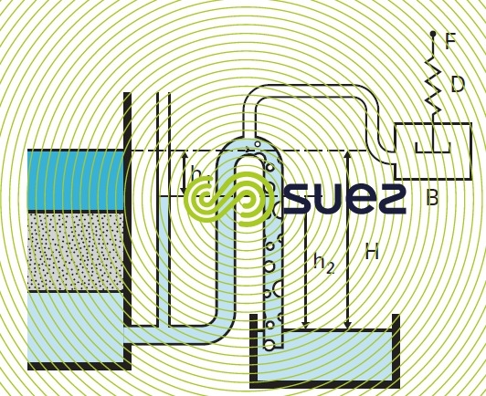
If h1 represents the pressure drop, with a clean filter, caused by the passage of the flow to be filtered through the filtering bed, the floor and the filtered water outlet pipe to the siphon neck, h2 represents the fouling depth available for the filtering bed.
All we need to do is, with a clean filter, to inject enough air to create a pressure drop h2 and, as the filtering bed becomes fouled up, to reduce the air flow down to zero so that h1 increases up to H.
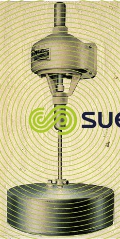
partialisation unit (photo 10)
This is the control mechanism used to inject air into the top of the siphon to control its flow rate. The air flows through an opening. The section of this opening is altered by a moving component comprising a float and a return spring (figure 21).
level control using a valve: the Regulazur
The Regulazur (figure 22) is a control system developed by SUEZ using a programmable logic controller: the programmable logic controller actuates a butterfly valve (2) mounted on the filter water discharge pipe, creating a secondary head loss that compensates for filter fouling. The Régulazur regulates valve movements according to the signals delivered by the level sensor (6) and valve positionning sensor (8) so that :
- under stabilised operating conditions, the level of water in the filter remains close to its set point, irrespective of the flow rate;
- during restarts after a wash, or in the event of a change to the flow rate, the filter gradually comes up to speed, without any surges, in order to minimise outlet turbidity peaks.
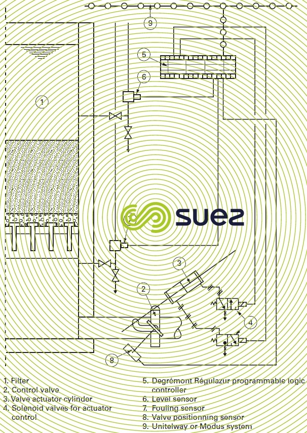
A sensor (7) also informs the Régulazur of filter bed fouling levels and can actuate a backwash accordingly when maximum fouling has been reached.
Each filter is equipped with a Régulazur; the Régulazurs on the battery of filters are usually connected to a communication system (Unitelway, Modbus…); the main programmable logic controller is also connected to this communication system.
In this case :
- equipment specific to each filter (valves, sensors …) is connected to the relevant Regulazur that transmits data delivered by the sensors to which it is connected, to the main programmable logic controller via the system;
- valves and sensors on washing equipment and on auxiliary equipment common to the filter battery are connected to the main programmable logic controller.
The main programmable logic controller is responsible for managing the operation and the washing of the entire filter battery: it actuates the control mechanism and the valves for each filter by transmitting its signals via the Régulazur which in turn controls the controller valve setting.
The Regulazur combines all the principles that are characteristic of good filter control and, consequently, constitutes the most advanced solution in this field :
- stable instantaneous output and slow flow rate fluctuations each time the plant operating conditions change, thus resulting in a consistent filtered water quality;
- constant level, upstream control: the stable water depth over the filter bed avoids the danger of occasional vacuums forming within the filter bed;
- reliability: use of a few, simple and reliable sensors and of networked, proven technology, programmable logic controllers;
- optimized battery management, incorporating backwash management and control.
Video presentation or the operating principle of the Regulazur™ III
Bookmark tool
Click on the bookmark tool, highlight the last read paragraph to continue your reading later
