


barscreening
Reading time:utilisation conditions
Barscreening, the first unit in a treatment system, is essential in surface water and waste water. It is used to:
- protect downstream structures from the arrival of large objects that could cause blockages in connecting pipelines, and even in the various units constituting the plant;
- separate and easily remove bulky matter carried by raw water and that could jeopardise water and sludge treatment effectiveness, or at least complicate treatment implementation and operation.
The same screens are sometimes used to remove fibres from sludge.
The operation is more or less effective, depending on the gap separating the screen bars. There is:
- preliminary barscreening, where the gap is greater than 40 mm;
- medium barscreening, with a 40 to10 mm gap;
- fine barscreening, with a 10 to 6 mm gap;
- straining, with a 6 to 0.5 mm gap.
Depending on the types of water, sludge and treatment selected, the barscreening unit can combine one or more mesh types; for instance, an UWW plant comprising a Densadeg followed by a Biofor, fed by a combined system, will include 80 mm preliminary barscreening, 6 mm fine barscreening and 3 mm straining. These systems can be installed one behind the other in the same barscreening unit, or separately, on the water upstream from a critical treatment stage.
At present, the general aim consisting in reducing manual operations in barscreening units means that an increasing level of automation is required, even in the case of the smaller plants.
Manual barscreening is often installed as a safety measure on automatic barscreening systems or on by-passes.
A by-pass becomes inevitable when there is a sudden influx of plant matter (autumn leaves) that tends to block the bar screen rack.
As a rule, the following spacing applies:
- for surface water, usually between 20 and 40 mm (upstream from the strainers);
- for urban wastewater, on raw water, between 80 and 10 mm;
- for sludge after a treatment that requires 10 mm, or even less, fine barscreening;
- for some industrial effluents, especially agri-food, fine barscreening is absolutely essential and may sometimes be followed by straining.
The waste products collected are then stored in a container having a capacity that is calculated according to an acceptable removal operation frequency
hydraulic design and fouling
principle
The speed of passage through the bars must be sufficient to ensure that the matter is brought up against the screen without, notwithstanding, generating too high a head loss or causing in-depth bar fouling or allowing matter to flow through with the water.
approach velocity
This velocity must not exceed 0.6 to 0.7 m · s–1 at peak throughput, in the delivery channel. As this is a low velocity, it is therefore inevitable that there will be deposits upstream from the screen and that these must be anticipated (installation of a permanent or sequenced stirring system).
speed of passage between the bars
This speed is generally between 0.5 and 1 m · s–1 and can reach 1.00 to 1.20 m · s–1 at maximum throughput.
These speeds apply to the free passage section, with a fouled screen.
fouling
The acceptable level of fouling (as a percentage of the free wetted section) depends on water quality and on the system used for clearing waste from the screens.
In the case of automatic screens and strainers:
- spacing > 10 mm approximately 25%
- spacing 5 to 10 mm approximately 50%
- spacing < 5 mm approximately 75%
With regard to manually cleaned screens, the surface area of the submerged screen must be over designed in order to avoid excessively frequent cleaning. Head loss will be approximately 10 cm.
automatic control
The bar screen’s cleaning mechanism usually works intermittently. The cleaning system is controlled on the one hand by a cyclic system operating at set intervals (between 1 minute and 1 hour) and for adjustable periods (between 1 and 15 minutes) and on the other hand by an upstream or differential head loss indicator, and a safety level indicator activating continuous operation.
When the screen is positioned downstream from the pumping unit, this actuation can be linked to pump start-up.
protection
Automatic screens are equipped with load limiters to avoid damage to the equipment in the event of major fouling resulting in an overload or a blockage.
Alternate cleaning automatic screens incorporate an arrangement that automatically stops the rake at a point outside the bar screen rack, in order to prevent any jamming or abnormal torque on restart.
different screen types
manually cleaned screens
Manually cleaned screens are straight and made of round or rectangular bars. They can be fitted vertically or sloping (60° to 80° from the horizontal) to make it easier to lift screening waste. They are occasionally mobile (on slides) or may pivot so that the downstream channel can be cleaned when the latter is covered over. In wastewater lifting units, these screens may be replaced by perforated baskets that can be raised, thereby avoiding the need for access. These systems do not make for easy handling and cleaning. That is why they are normally used on an intermittent basis (by-pass).
automatically cleaned screens
screens cleaned on the upstream side
Their bar screen racks are normally made of bars having a rectangular or trapezoid section (reducing the danger of jamming by solids) with sharp or rounded edges. Some equipment is well suited to fine bar-screening (that can go as far as straining) by using an appropriate bar screen rack (Johnson type, with gaps of 0.5 to several mm) or a perforated metal sheet. Debris is removed downstream from the screen.
This screen comes in four main types
DC type curved screens (photo 2)
Having a 10 to 25 mm gap between bars, these screens have the advantage of a large section useful passage and of a simple mechanical design.
Four rakes mounted on the end of an arm that rotates round a horizontal axis are used to clean the screen rack. However, in order to avoid any risk of jamming, it is advisable to include a pebble trap upstream from the screen rack.
This type of screen is ideal for medium sized plant when the water is not excessively loaded and when the height the debris has to be lifted is limited.
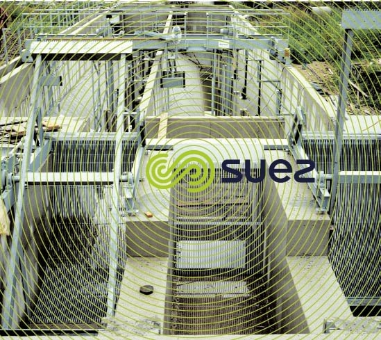

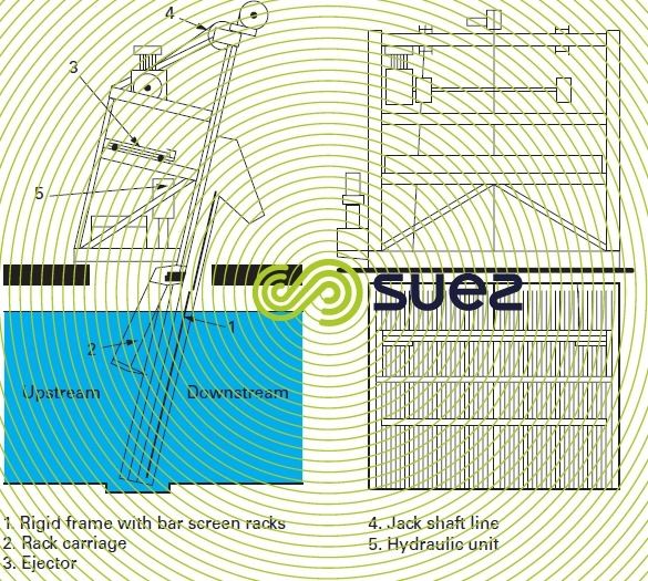
GC type alternating cleaning straight screns (figure 1 and photo 3)
These screens have bars separated by a 10 to 100 mm gap and are generally vertical or sloping at approximately 80° from the horizontal. The bar screen rack stops just above the maximum liquid level and is extended by a flap.
The bar screens are cleaned by scrapers and rakes driven by an endless chain system that lifts the waste up the entire bar screen rack and flap and then drops back to a position away from the bar screen rack. A powered waste removal system is often used to clear the top section.
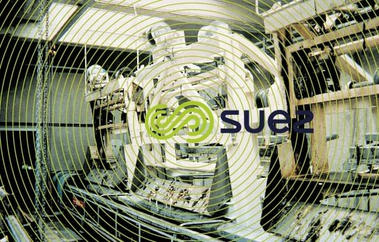
An extremely sturdy variant that can be used with very high bar screen racks (> 10 m) is the so-called climber screen where the rake is driven by a rack and pinion system (photo 4).
When the bar screens are required to process very high throughputs in excess of 30,000 m3·h–1 of lightly loaded water (taken from surface water), a mobile rake can be placed so that it only affects part of the bar screen rack and moves to the side after each cycle.
continuous moving bar screen racks
With a 3 to 15 mm gap between bars, these systems consist of a continuous chain bar screen rack. The teeth or hooks are mounted on pins and form a continuous chain. Waste is lifted and discharged backwards from the top.
The teeth are made up of arms and points. The elements are automatically cleaned as the points drop between the arms, a rotating brush completing the automatic cleaning process.
stair type rotary system
With bars spaced 3 to 15 mm apart, the bar screen rack comprises two groups of parallel blades; each group is configured like a stairway. The first is fixed and the second is mobile.
A set of hinged arms imparts a rotating motion to the moving blades. Thus, the waste is lifted one step at a time up to the discharge point.
screens cleaned on the downstream side
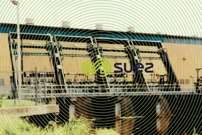
Some bar screens have a cleaning system that comprises continuous chains positioned downstream. With these systems, there is a danger that some of the residues collected will drop back into the downstream water. However, a preliminary bar screen that is cleaned on the downstream side can be used for water that is very heavily laden and requires a major extraction capacity (photo 5).
Bookmark tool
Click on the bookmark tool, highlight the last read paragraph to continue your reading later
