


structures
Reading time:pre-grit remover or ungraded waste pit
Consideration can be given to their inclusion when the following conditions are met:
- combined or partially separate system;
- absence of grit removal chambers on the outfall or chambers that are not maintained;
- shallow outfall slope (self-cleaning restricted to major rainfall incidents).
designing an ungraded waste pit
After examining the gravel, ceramics output from some installations, the following calculation formula was established to calculate minimum capacity.


V = volume in m3,
Cb = load in m3 of grit and gravel per m3 of raw water,
Qp = storm water flow rate in m3 · h–1,
h = number of rainstorm hours expressed in hours,
n = number of rainfall events associated with the filling of a tank (storms).
For Cb, we shall use: 50 · 10–6 m3 · m–3.
The area of the pit must be capable of a surface loading of approximately 800 m3·m–2·h–1. However, a larger pit would become a partial grit remover.
extracting ungraded waste grit and gravel
There are two possible solutions: installing a gantry or a beam over the pit with a grab, or extract using a gulley cleaner type vehicle.
In the first case, the extraction can be undertaken when the pit is water-filled.
In the second case, it is better to have two pits so that one can be isolated from the other.
pit ventilation
The odour and H2S emission aspect also needs to be taken into consideration because the products that will have been contained in the pit(s) will contain fermentable volatile matter. Appropriate ventilation then needs to be installed in conjunction with an H2S detector.
circular grit removers
These 3 to 8 m diameter cylindrical-conical structures have a 3 to 5 m liquid depth.
The grit drops down to a more or less sloping floor and is moved by hydraulic effect, falling into a central storage and recovery hopper. The floor sweep velocity remains virtually constant at a figure above 0.3 m · s–1. This is achieved by three means that are characteristic of this type of structure:
- the liquid mass is maintained in rotation by a vortex effect created by introducing the water at a tangent;
- the liquid mass is kept in rotation by a vertical shaft, mechanical rotating blade mixer. This device is used to maintain a constant specific output of approximately 10 to 20 W · m–3, regardless of flow rate and, therefore, ensures that the system operates at a virtually constant liquid level;
- the liquid mass gyrates (vertical plane) because suitable diffusers are used to inject air into a submerged central cylindrical baffle. This appliance also enables the system to operate at a virtually constant liquid level.
The grit collected is extracted by a pump or an air lift device and routed into a gravity drainage compartment or to a mechanical recovery system.
aerated rectangular grit removers
These structures can range from 4 m wide (single unit) to 8 m wide (double unit) and have a liquid depth of approximately 4 m and a maximum length of approximately 30 m. They are used to process major throughputs (up to 15,000 m3·h–1 for a double unit). The floor configuration depends on the grit recovery system selected.
Water is fed into one end of the structure and collected at the opposite end, through a submerged opening passing, quite often, over a downstream weir designed to maintain the water sheet level.
The longitudinal flow structure is equipped with an air injection system that runs along its entire length; this system is equipped with suitable air diffusers such as Vibrair, providing a specific aeration output in the region of 15 to 30 W · m–3. The liquid level can be kept virtually constant. The air injected produces a spiral flow and, through a turbulence effect, encourages the separation of the organic matter that has become bonded to the grit particles, ensuring that floating matter (including solidified grease) is partly eliminated.
Several different methods can be used to extract the grit automatically:
- a series of syncopated air lifts (extracting from lower level hoppers);
- a scraper bridge that scrapes the grit towards a pit at the end of the structure where the grit is recovered by means of a pump or a fixed air lift;
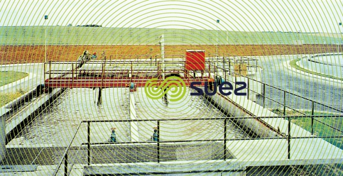
- a suction pump or air lift mounted on a moving bridge and discharging the diluted grit into a lateral evacuation chute (photo 8).

metallurgy » grit removers
Two grit removal techniques are used depending on the incoming water level.
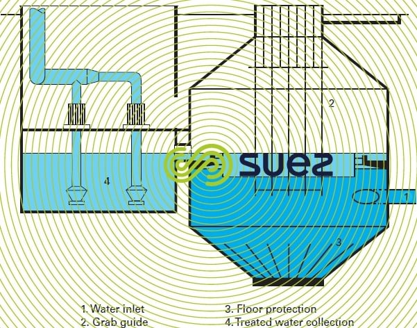
tangential separators (figure 6)
Often wrongly termed «hydrocyclones» because of the low centrifugal energy delivered; these mechanisms are used with incoming levels from the sewers that can drop down to – 10 m, in the case of rolling mills, strip mills or continuous casting. These cylindrical-conical structures play two roles:
- they separate discrete particles through vertical settling;
- they separate incoming oils by collecting the water from under the scum baffle.
Deposits continue to be collected using a grab.
Constructed by SUEZ with diameters ranging from 4 to 32 m, these structures are installed upstream from settling tanks or filters. Their filtering capacity then has to be brought down to 120 mm (see also open recirculating systems).
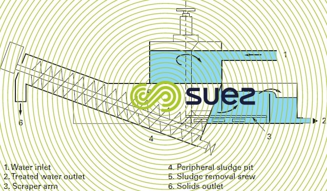
« classifier » separators
Used primarily in steel mills to perform a grit removal function only, removing discrete particles measuring more than 200 or 250 µm, these structures are installed upstream from thickening sedimentation tanks and protect sludge pumps and dewatering equipment.
Constructed by SUEZ, these 5 to 12 m diameter structures are usually supplied via overhead pipelines and comprise a very rapid cylindrical settling zone, with a shallow water depth. A centrally driven, diametral scraper arm removes sediments to an outer pit from which these sediments are extracted by a screw or by a reciprocating rake (figure 7).
Bookmark tool
Click on the bookmark tool, highlight the last read paragraph to continue your reading later
