


open recirculating systems
Reading time:coke plants
Open recirculating systems include:
- the dust removal system used for coke quenching; this system is equipped with rectangular scraped settling tanks. The overflow from these tanks is partially recycled. We should also note the following:
- 50% of water is evaporated during the quenching process;
- salinity restrictions for the feed water limiting the concentrations of various salts and especially of chlorides;
- the furnace loading and/or preheating flue gas scrubbing dust removal circuit is equipped with settling tanks where the overflow is also partly recycled for use as make-up water for the quenching system.
blast furnaces
This unit mainly consists of a gas scrubbing system.
Typically, a dry purification system is used to eliminate particles > 75 μm followed by a wet treatment for the remaining particles (approximately 3 g · L–1). One possible treatment has been outlined in figure 52 which mainly applies to particle separation in the thickening tanks, reducing hardness, if necessary, by lime softening, the overflow being cooled before being recycled to the scrubbers.
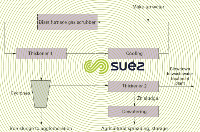

Occasionally, there will be foaming problems but these can easily be resolved using anti-foaming agents.
Sludge is occasionally cycloned to separate zinc from iron. This 80% dry solids content sludge is then recycled to the agglomeration system (zinc is a pollutant found in blast furnaces; it will vaporise at the heart of a blast furnace and condense at the “throat”, causing major damage). The overflow from the cyclones is routed to a specific thickening tank from which the supernatant is returned to the wash system; zinc sludge is dewatered and stored. With this scheme, 90% of the zinc is removed and 60% of the solids are recycled. Blowdown from the wash system may sometimes contain cyanides that will need to be oxidised before being sent to the main treatment plant.
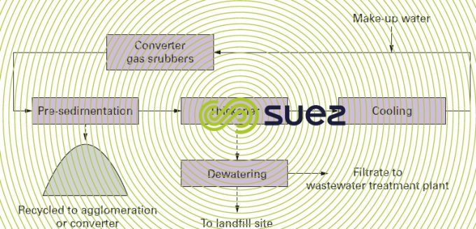
steel converters
These units mainly consist of a gas scrubbing system.
Figure 53 identifies possible treatments that mainly include:
- pre-sedimentation with sludge lifted by screws or "vibrating ladders";
- thickening (after flocculation, which is necessary in most cases);
- alkalinity addition injecting Na2CO3 at the settling tank inlet.
Water treated in this way is cooled before being recycled to the washers; presedimentation sludge is recycled as a load in the converter (this sludge contains a lot of lime, magnesium oxide and calcium carbonate); thickening tank sludge is dewatered and then sent to a landfill.
At present, research is being undertaken into recycling this waste to the agglomeration system or directly to the converter (however, concentration levels of various elements have to be monitored).
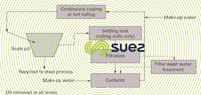
continuous casting and hot rolling
Continuos casting and hot rolling units are equipped with closed systems for cooling ingot moulds, furnaces, rotating machines and inspection equipment that are conditioned and that do not produce effluent that requires treatment.
However, these units also include spraying and cooling systems that are processed and recycled and where the main pollutants are oil, grease and scales.
The most commonly applied treatment scheme used for most of these plants includes:
- a cylindrical, tangentially fed scale pit (normally designated ‘hydro cyclone’) that holds back the most granular particles (> 200-250 μm) together with some of the lubrication and rolling oils. These oils are collected by floating type surface oil skimmers (nénuphar [water lily], diskoil, liftoil…) while a grab is used to extract the scale for recycling;
- an API type rectangular settling tank (only for hot rolling applications) where bottom scraping is used to remove fine scale together with the oil collected by surface oil skimmers. A bucket is used to remove the scale which is then spread over a draining area before being recycled (depending on the quantity of oil it contains);
- a battery of sand filters is used to achieve thorough elimination of oil and fine scale. The wash water from these filters is clarified before being recycled, with filtered water, to the spraying system via cooling towers.
Attention should be given to the different oil concentrations and scale particle sizes found in casting and rolling processes.
Special attention also needs to be given to flame cutting recovery systems at the end of a casting line (recurrent problem of blocked collection systems).
These systems are rarely blown down and no blowdown carried out will be treated separately before being routed to a general processing plant.
Figure 54 illustrates the general treatment scheme applicable to these units.
Bookmark tool
Click on the bookmark tool, highlight the last read paragraph to continue your reading later
