


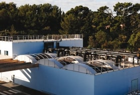
Sichuan Petro, Chengdu, Chine refinery
Reading time:One of the largest gras-root refineries (240 kbpd) and petrochemical complexes (800 kT/yr ethylene) in China that was commissioned in 2014. Due to the location of Chengdu some 1700 km away from the sea the discharges standards (COD < 60 ppm) to the river are very strict. Petrochina implemented a maximum reuse strategy for wastewater up to 75% and a dedicated treatment for the removal of hard COD from the reverse osmosis reject stream with the Oxyblue process.
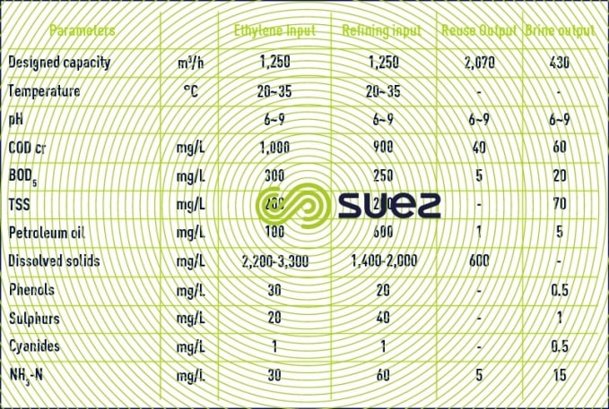

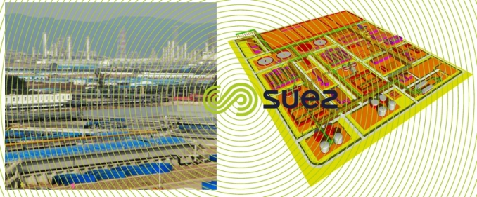
To respond to the above requirements two parallel identical treatment lines were installed for the refinery and the petrochemical complex for 1250 m3/hr with DCI circular API separators, catalitic sulphide oxydation, two-stage dissolved air flotation, nitrification-denitrification biotreaters, clarifiers and Densadeg lamellar separators.
The effluent from these four lines is further treated in a single combined water reuse line. The recycled water is used for boiler feedwater. The hard COD after the biological treatment is oxidised with ozone upstream the reverse osmosis unit and downstream in the reverse osmosis reject, followed each time by a biological filtration stage with Biofor biological aerated immerged filters.
Clean stormwater from the industrial complex is collected separately and treated in a dedicated clean water treatment line with dissolved air flotation and Aquazur V filters.
Pemex Salina Cruz (Mexico)
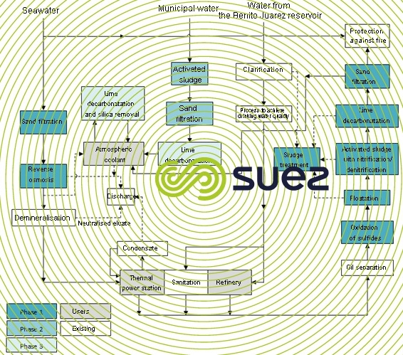
Until 1998, the largest Mexican oil refinery (330,000 barrels per day) was supplied with reservoir water (2,920 m3·h–1) and its effluent was de-oiled and “treated” in non-aerated lagoons before being discharged to the sea. In order to conserve reservoir water for human consumption, Pemex initiated a program that became a three-phase BOT (Build, Operate, Transfer). Table 24 summarised the design basis and/or actual results regarding reduction of reservoir water usage (all figures shown as m3·h–1).
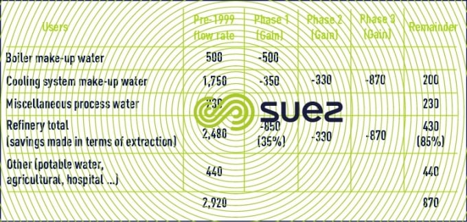
At the end of phase 3, the refinery’s reservoir water consumption will be limited to 430 m3·h–1, representing 85%reduction compared with 1988. It should be noted that, going further, cooling tower concentration levels will have to be increased further and, in order to avoid corrosion and in addition to current treatments, a make-up water demineralisation system will have to be introduced ( IWW and UWW ).
phase 1 (1999)
This phase comprises :
- seawater desalination of 560 m3·h–1 employing reverse osmosis, to feed boilers via existing ion exchangers;
- total recycling of process wastewater (350 m3·h–1) ppumped from existing lagoons via flotation, a nitrifying biological unit followed by lime softening in a Densadeg clarifier, and single-layer sand filtration at a rate of 350 m3·h–1. This water is reused for fire water and as make-up water for the cooling towers.
Table 25 provides the properties of the IWW (forecast and actual) and of the recycled treated water.
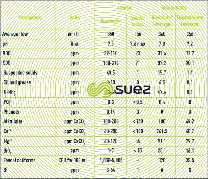
It can be seen that lagooning is the main factor responsible for the discrepancy between forecasts and actual raw water, and that the treated water does not have any properties that adversely affect the cooling system because its concentration factor is approximately 3; in particular, suspended solids, BOD, NH4 and PO4 levels after treatment are very low.
phase 2 (2002)
A municipal wastewater treatment plant (town of Salina Cruz) was built In order to reduce water usage even further. After a traditional low-load biological treatment for nitrification and denitrification, effluent undergoes tertiary treatment before being combined with treated IWW effluent.
phase 3
Taking matters further, a proposal was submitted for increasing cooling tower cycles of concentration from approximately 3 to 8. However, this assumes that:
- make-up water hardness is improved; as this water is mainly provided from UWW, it must be softened;
- the quality of recirculation water in the cooling system is maintained by reducing its hardness as well as its silica content via a sidestream treatment including softening/silica removal via a Densadeg clarifier, utilising lime and supplemental magnesium salt to enhance silica removal.
Figure 37 illustrates the three-phase sequence (different colours) and the anticipated final plant design.
Bookmark tool
Click on the bookmark tool, highlight the last read paragraph to continue your reading later
