


other references
Reading time:Shanghai Chemical Industry Park
The Shanghai Chemical Industry Park (SCIP) is the first industrial zone specialised in petrochemical development and fine chemistry companies, as well as one of Shanghai’s four industrial production sites. It has been built according to an innovative and large-scale, international design in order to be able to provide industrial park investors with the best environment by combining production projects with public services, logistics, environmental protection and administrative services.
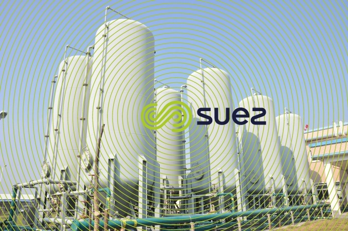
SCIP (photo 25 and 26) has been defined as one of the largest and most integrated and advanced sites in the Asian petrochemical industry.

(SCIP SFWD) is responsible for providing industrial water to the Shanghai Chemical Industry Park and treating its wastewater. This co-enterprise was created in 2002.
Based on SUEZ, the JV has built since 2003 the process water treatment plant, the wastewater treatment plant ( WWTP ) and the demineralised water production plant. SCIP’s purpose is to provide suitable services to clients as well as innovative solution to meet the challenges of industry.
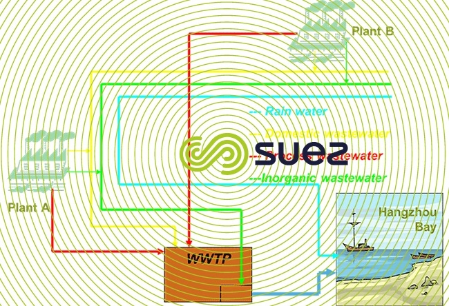
The chemical industry produces a wide variety of effluents (complex compositions, toxic chemicals, unstable discharged volumes and fluctuations in effluent quality). In most industrial parks, the various types of effluent are transferred to a treatment plant using shared pipelines, as occurs in domestic wastewater treatment processes.
However, this type of management may lead to difficulties in operations due to the presence of inhibitors in some of the effluent and which contaminate all the effluent. This is why the effluent here has been separated into four groups :
- stormwater, inorganic wastewater, domestic wastewater and process wastewater.
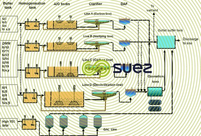
The wastewater plant’s treatment capacity has been designed for 50,000m3/day and its construction is in stages. The wastewater treatment plant is currently 36,500m3/day with 4 independent biological treatment lines and 1 GAC line. Each biological line contains a homogenisation tanks, a biological system and a polishing, tertiary treatment process which has a DAF tank for each line and, for all lines, an O3 oxidation process. Oxidation with O3 plays an active role on residual COD and eliminating colour.
SFWD intends to continue to invest in similar facilities and to permanently optimise operations so that an even higher safety margin can be achieved.
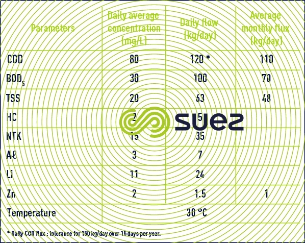
Treated effluent must comply to the local, Shanghai Grade II « Integrated wastewater discharge standard ». In addition, Grade I quality standards (DB 31 / 199-2009), will come into force on 1st July 2017.
The main parameters (table 32) are described here after :
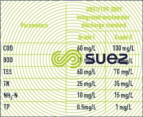
The complexity in the types of wastewater from the different industries requires the establishment of a plant, appropriate buffer capacities, emergency tanks and an advanced and optimised monitoring system from effluent input to its output.
Ineos Verdun
background, objectives and needs
- Effluent treatment coming from the Ineos plant and the new biodiesel manufacturing plant. Before the implementation of the new plant, the effluent was treated and mixed with agri-food effluent in an aerobic biological wastewater treatment plant.
- Compliance to discharge standards required in the Prefectoral Order
- Following pilot tests and given the good level of biodegradability of effluent with a favourable CODt/ BOD5t< 2, two-stage biological treatment was chosen: anaerobic digestion + activated sludge.
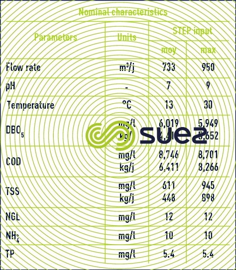
main characteristics of the effluent to be treated
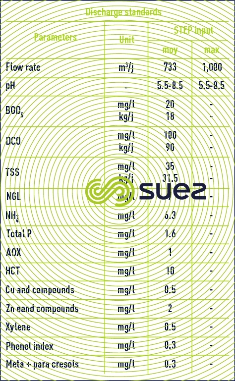
main discharge standards
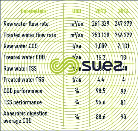
results obtained
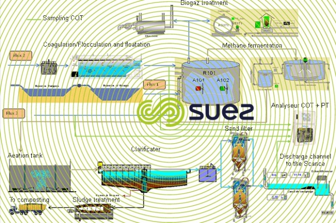
facility description and diagram
- Three different streams are treated :
Stream 1: water from old plant + stormwater
Stream 2: water from biodiesel plant + oil
Stream 3: boiler purging water and purges of the cooling towers
- Pretreatment of oily effluent from stream 2 using Serflo-type floatation
- Hydrolysis of oils from stream 2 then anaerobic digestion or treatment of oils with sludge in a centrifuge.
After having been appropriately mixed and homogenised, the different streams are treated in a 1400m3 Analift-type anaerobic digestion reactor
- Effluent is heated using a heat exchanger :
- a primary exchanger to recover heat from the effluent leaving the settling tank from the anaerobic digestion unit.
- a secondary exchanger fed by a mixed-burner boiler.
- Following settling, sludge is recirculated through the anaerobic digestion unit and the surnatant is sent to the aerobic polishing process; aeration, and stirring is carried out by immersed aerators.
At the clarification tank outlet treated water is sent to sand filters.
- Sludge is dewatered via centrifuge.
the Lanxess factory, Lillebonne, France
The Lanxess Elastomeres Factory at Lillebonne (76, France) is specialised in the production of rubber materials for the tyre industry and the manufacture of food plastics. The production capacity is 140,000 T/year of rubber.
With overall satisfactory operations and in order to remain compliant to the site’s Prefectoral Order, in particular concerning TSS and COD, the plant’s design must take into account the change in factory’s production with the emergence of soluble COD, not treated by the physico-chemical process.
characteristics of the water to be treated
The LANXESS factory operates non-stop, 365 days a year. Effluent is therefore produced 24 hours a day, 7 days a week.
The effluent comes from different sources :
- regeneration of the demineralisation chain
- cooling tower blowdown
- various leakage of clean or only slightly polluted water
- process water boiler blowdown
- process water
- stripping tower blowdown
- extruder extraction
- cyclone blowdown
- various rinsing operations
Effluent, although only slightly polluted, varies greatly and has the following characteristics in table 36 :
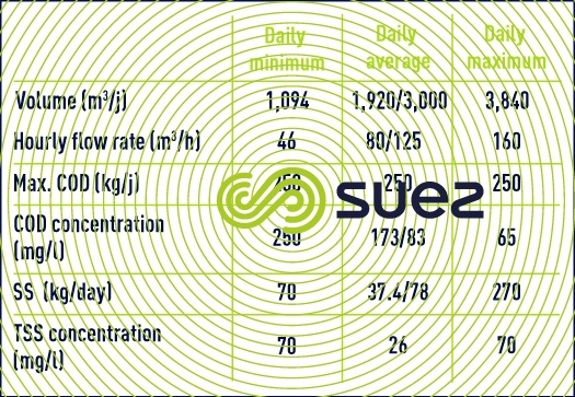
The discharge limits targeted by Lanxess Elastomeres are summarised in the table below :
the treatment process chosen for Lanxess Elastomeres
- the existing buffer tank with homogenisation by deploying immersed stirrers
- a primary physico-chemical treatment using coagulation/flocculation and floatation processes
- followed by a sand filtration
- ending with the treatment of excess COD by adsorption on granular activated carbon ( GAC ).
Given that LANXESS ESLASTOMERES’ production will change in the future with higher residual COD, the possibility to develop the treatment process to include ozone was integrated.
client satisfaction
Good feedback from the client. High level of requirements for this high level SEVESO site with highly specific technical specifications (threshold values are equal to petrochemical requirements).
DOW factory installation (formely Rohm and Haas)
objectives and needs
The DOW Factory at Chauny (formerly Rohm & Haas) located in Aisne county, is one of the world’s main ion exchange resin production sites.
The factory has a high-performance WWTP built by SUEZ 30 years ago.
As a polishing treatment before discharge into the Oise River, DOW decided to add an organo-halogen compound ( AOX ) treatment plant.
Ultrafiltration and ozone treatment processes have been planned but these attractive solutions were unable to guarantee that the desired quality of the water discharged could be met under all circumstances. Neither could they guarantee sufficient safety margins.
The GAC filtration process gave the better results by being able to meet the specifications set. The Client therefore chose the GAC solution and preferred installing a non-mobile solution in order to reduce operating costs.
main characteristics of effluent to be treated and discharge standards
Water discharged from the existing plant was compliant with discharge standards, but had occasional AOX concentration levels of up to 15mg/L. The facility’s AOX concentration objective is < 1 mg/L.
innovative facility design
The facility has 2 lines of 3 activated carbon filters. Without taking any risks in regards to discharges and in order to optimise activated carbon consumption, each of the 2 lines allows operations to be conducted is series or in parallel series.
Effluent first crosses 2 filters containing the oldest carbon. Less saturated carbon in the 3rd series filter provides a safety margin.
The PLC manages the automatic opening of valves in order to optimise filtration and maximum saturation of the activated carbon.
results obtained
The quality of effluent discharged is entirely compliant. Besides the removal of AOX, the treatment process significant lowers in the effluent’s colour and COD which is always less than 100mg/L. The facility allows excellent quality and safe effluent to be discharged compared to the discharge standard values required.
GAC consumption is lower than forecasted. The facility allows GAC to be used up to its total saturation.
As the reliable measurement of AOX is very difficult, especially in the case of chloride interference, DOW deployed a high-performance analyser which enabled measured and reliable results accepted by the self-analysis authorities to be obtained and activated carbon renewals to be significantly optimised.
construction and commissioning
Starting from the confirmed service order, the plant was commissioned in less than 9 months, including civil engineering works.
Our client was fully satisfied with compliance to deadlines and budget as well as the performance obtained.
Faprogi factory located at Rambouillet (78, France), L’Oréal Group
The factory produces an annual average of 54,000 m3/year of wastewater. FAPROGI wanted to be able to reuse this water for cleaning its production reactors. FAPROGI therefore contracted SUEZ for the construction of an effluent treatment unit at the current wastewater treatment plant’s outlet, enabling :
- the quality of the water sent to the storage tank to be compliant
- the quality of water sent to the town (via the discharge agreement) to be compliant
water characteristics
Desired production flow rate : 147 m3/day
Operation : 5.5 days per week 24h/24
quality of raw water
The sizing values retained are as follows :
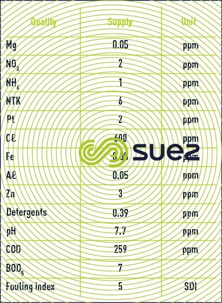
Raw water will be taken from the existing ultrafiltrated water storage tank.
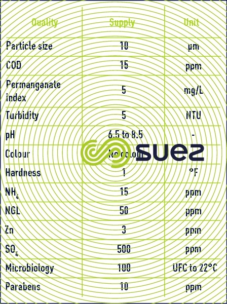
treated water quality
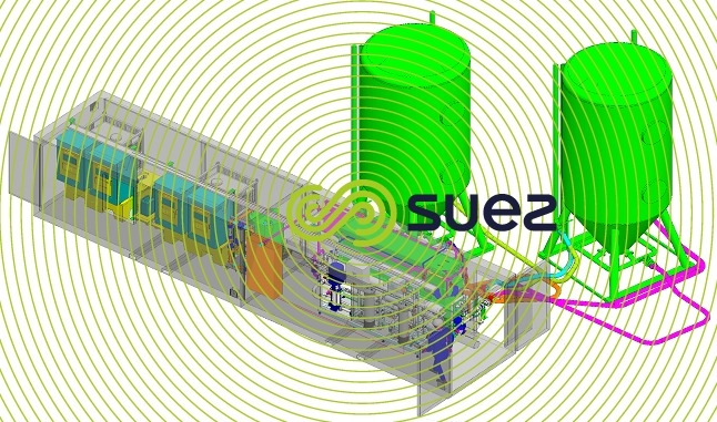
facility description (figure 48)
The technical solution proposed is based on a reverse osmosis treatment unit capable of treating water loaded with mineral salts and COD.
The raw water to be treated being ultrafiltrated water leaving the WWTP, the necessary precautions need to be taken in relation to :
- The fouling index.
- The risk of a bioflim developing linked to residual BOD5.
- The risk of fouling through scaling due to the calcium.
The treatment line is comprised of :
- a) Partial adsorption of organic nitrogen and COD by activated carbon filters
In order to obtain the maximum operational safety for the activated carbon unit, 2 filters in series with the shifting of new activated carbon into second position after each rotation has been implemented.
- b) Reverse osmosis ensures the effective treatment of dissolved elements in the water and produces water with a constant quality.
The osmosis unit starts up upon contact with the lower level of the osmosed water receiving tank.
This equipment allows 95 to 99.6% of the mineral load to be removed and 99.9% of the bacterial load to be reduced.
In order to avoid having to build a specific treatment building, the equipment was installed in 2 x 20-foot containers, in a fixed linked position.
All the material was pre-assembled before arriving on site.
optimisation provided
The optimisation of the activated carbon used has been achieved with a chemical, manufactured by activating steam, and acid scrubbing to remove most of the extractable minerals, which allows rinsing operations to be minimised without impacting pH.
« Mane et fils » compagny
background, objectives and requirements
The company V.MANE&FILS owns two sites at Bar-sur-Loup: the Notre-Dame and Sarrée factories, specialised in the production fragrance oil for perfume.
The effluent generated by both sites was treated at a wastewater treatment plant located at the Notre Dame site.
The modification of the Prefectoral Order imposed new requirements regarding the quality of effluent discharge into the natural environment, as from 1 September 2012.
incoming raw effluent characteristics
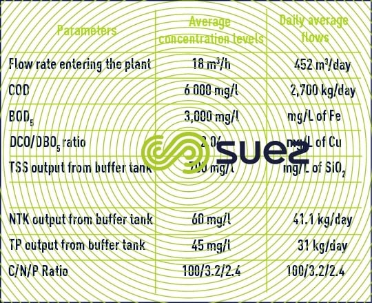
The « carbon/nitrogen/phosphorous” nutrients ratio for the biological treatment of effluent shows:
- A lack of nitrogen, offset by adding urea in the buffer tank
- A slight excess in phosphorous which will require treatment
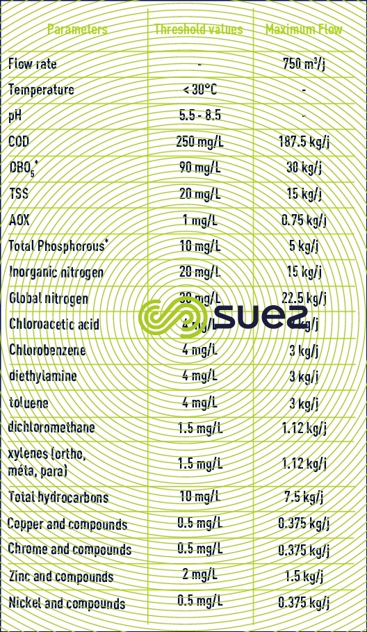
quality of discharged effluent
The quality of discharged effluent must be compliant with the additional revision of the Prefectoral Order, the threshold values of which are given in the table below:
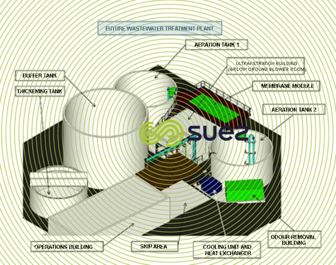
sizing the wastewater treatment plant
The treatment process deployed meant integrating an organic membrane filtration unit into the existing plant in order to separate treated water and sludge instead of and in place of the existing settling tanks.
pretreatment
- aeration tanks
The wastewater treatment plant has two identical aeration tanks. Two immerged settling tanks were incorporated into the aeration tanks. Following the removal of the settling tanks, both aeration tanks were reused as aerators, as initially designed.
organic membrane bioreactor
Treated water/biological sludge separation is carried out by the membranes.
permeate tank for backwashing allowing
- supply to the industrial water skid
- membranes to be washed during backwash operations.
sludge treatment process
Sludge is pumped from the bottom of the thickening tank by 2 progressive cavity screw pumps (1 in operation, and 1 for emergency back-up) and is dewatered by a belt filter press before being disposed of in a suitable disposal process.
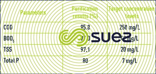
the main results obtained for treated water

The results obtained are compliant with requirements in the revised Prefectoral Order.
Bookmark tool
Click on the bookmark tool, highlight the last read paragraph to continue your reading later
