


refinery
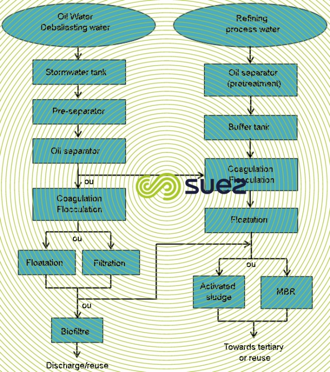
Reading time:Wastewater treatment will vary depending on the nature, age and size of the refinery; however, figure 33 illustrates a typical approach (one that is increasingly encountered) for separating effluent into at least three systems:
- «contaminated» storm water;
- process water;
- deballasting water.
This segregation becomes essential when the objective is to optimise recycling, after processing, of low salinity effluent to cooling, fire water storage and process systems and even to LP or MP - HP boilers.

AT the beginning of the standard process water treatment line, occasionally shared with the treatment of stormwater, there is a tank receiving effluent. This tank’s design depends on the layout of the primary oil separators. If they are located underground, the plant distributes the water through gravity to the adjacent separators. If they are located above the ground, which is common, a pumping station needs to be added. In order to avoid the formation of an emulsion due to the presence of insoluble oils which risk reducing the oil separator’s performance, then low shear pumps should preferably be used. A screen is also required to protect the mechanical equipment from solid debris.
primary oil separation
Oil separation is performed by using standard separators, such as API or DCI. The separator produces two types of waste streams. Oil is recovered on the surface and sent to the refinery (following a possible concentration stage) and the sludge at the bottom is sent to a sludge treatment system :

buffer tank
The stages located downstream to the buffer tank (coagulation/flocculation and biological treatment) are more affected by fluctuations in loads than the primary oil separation stage. The buffer tank allows the effluent leaving the primary oil separation stage to be balanced in order to absorb load fluctuations. The typical retention time for this stage is 18 to 24 hours, depending upon the flow rate.
The buffer tank is equipped with a stirring system which makes its content uniform. Stirring is often carried out by aeration.
The buffer tank also has a role in maintaining the output temperature lower than 40°C. Indeed, refinery effluent can reach temperatures of between 40 and 60°C. These temperatures are suitable for the primary oil separation stage because high temperatures encourage water/oil to separate. However, for the flotation and biological treatment stages a temperature of 38°C is generally considered in the design. Consequently, cooling is necessary. In the temperate climates of Northern Europe, the simplest method is to air cool. In areas where the ambient temperature is higher, heat exchangers and water cooling systems are used. If the temperature of cooling water is not low enough, a cooling unit is required.
In the case of high sulphur concentration (higher than 10mg/L) the buffer tank may be used to perform catalytic oxidation by adding ferric chloride, whilst maintaining the aeration required for oxidation.
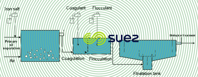
coagulation – flocculation – flotation
Although primary oil separation significantly reduces the load in insoluble oils, the output concentration levels in primary treatment remain higher than those tolerated by biological treatment processes (less than 10mg/L). The level required may be obtained by a second oil separation stage and by chemically assisted flotation. Coagulation and flocculation tanks as well as linked dosing systems, are placed upstream to the flotation process. Soluble organic matter is not removed during this stage.
biological treatment
Biological treatment may be either an activated sludge process or an MBR process. However, regarding the MBR process, the input oil concentration level must be controlled because a concentration level which is too high may damage membrane operation.

sludge treatment
The sludge treatment stage generally has a storage tank and a dewatering stage. A centrifuge settling tank is the technology most used for dewatering sludge. The dewatered sludge cake is then sent to a landfill.
oily storm water
Oily storm water, generated in variable and sometimes very high flow rates, is stored in a storm water tank. The oil is removed via API separation and further through filtration or flotation and may occasionally be discharged at this stage.
Depending on its BOD5 and phenol concentrations, it may undergo biological treatment if necessary before being discharged; however, in this case, it is often routed to the process water stream.
Should this not be the case, in order to reuse it, for instance as make-up cooling water, tertiary treatment will be required for removal of suspended solids as well as, occasionally, residual phenols. This treatment can be carried out using biofilters (trickling filters, Biofor).
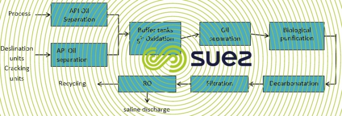
process water
Process water emanates from refinery units (AD, VD, FCC ,HDS, miscellaneous cracking, visbreaking…). Effluent produced by desalinators and the FCC (catalytic crackers) are the most saline and often polluted with sulphides which justifies a preliminary stripping and/or oxidation treatment (figure 34) before undergoing oil removal by flotation and biological treatment.
Separating this effluent from the remainder of the effluents allows better sulphide treatment and, if necessary, the separated effluent can then be returned to the ballast water line when its salinity is excessive.
Figure 35 illustrates a complete treatment process including recycling process water as boiler make-up water. It should be noted that, in this case, ballast water (often seawater) must be processed and discharged separately because it is toosaline for reuse.
transport and deballasting water
Deballasting water is transferred at a high rate to a ground-level buffer tank for storage. It is then extracted at a moderate flow rate, mixed with industrial wastewater from the refinery and undergoes treatment. It is then, most of the time, discharged into the sea.
Due to its storage over a few days, it has settled well and the treatment process simply requires:
- oil separation for safety precautions, removing the peaks of hydrocarbon ;
- dissolved air flotation with an organic coagulant enabling good oil separation.
Due to this and the fact that deballasting water volumes are currently much lower than in the past, this water is often treated in a stormwater treatment process.
three typical examples
These examples illustrate the layout of treatment lines and results achieved with increased internal recycling and/or reuse of UWW, thus limiting extractions from the natural environment but resulting in the need to process more concentrated effluent.
NPC refinery in Tabriz (Iran)
This is a simple refinery that includes catalytic reforming that supplies a unit producing aromatics and synthetic rubber.
The process wastewater flow is 200 m3·h–1 during dry weather and via a 6 000 m³ storage facility, an additional, 30 m3·h–1 of contaminated storm water (instantaneous flow rate of 3 000 m3·h–1).
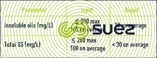
Table 22 provides contaminant concentrations (in mg · L–1) and plant discharge requirements.
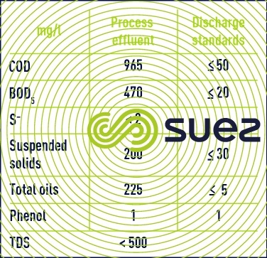
This recently constructed plant (1996-1998) is characteristic of water conservation practices. Therefore, it processes fairly concentrated effluent.
It should be noted that sanitary wastewater is segregated and treated separately in an municipal type biological system.
The IWW treatment line includes an API separator, an equalisation tank, a flotation unit and a low-load biological tank followed by clarification.
The plant effluent water was required to meet reuse quality and to meet COD < 50 mg · L–1 (approximately 95% reduction), thus tertiary treatment was required.
It comprises a clarifier followed by three twin-layer filters and three activated carbon filters.
The sludge treatment process includes centrifugation of waste activated sludge which is then routed to an incinerator with all the oily sludge (API, slops, sludge from the floor of the tank and the flotation cell) together with waste from the synthetic rubber units (Butadiene, SBR, SBL).
Note : SUEZ has provided a series of systems for processing feed and discharge water for this refinery (see also biological treatment).
Bookmark tool
Click on the bookmark tool, highlight the last read paragraph to continue your reading later
