


treating effluent produced when removing sulfur from electricity generating plant
Reading time:origin and quality of FGD effluent
We can note that a 750 MW power station will typically generate 2.5 M Nm3·h–1 of flue gases from which 4 to 5 tons of SO2 have to be removed per hour.
The most conventional process consists in scrubbing the gases in two stages using the wet scrubber method:
- the flue gases are cooled to approximately 50°C by a semi-closed system having a pH of 0.5, part of which is blown down to the effluent treatment system;
- the gas is scrubbed using a CaCO3 or Ca(OH)2 slurry maintained at a pH of approximately 4, part of which is blown down to the wastewater treatment system.
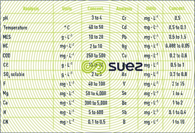
These blowdowns then have to be treated to bring them into compliance with federal or local discharge standards. These wastewaters typically consist of acid brine containing suspended gypsum and either SO2 or a mixture of SO2 + NOx depending on the case. They also contain a large number of metals in concentrations that are typically higher than the normal standards on discharges (extremely variable depending on the country or locality concerned) (table 26). This treatment is generally known as FGD whereas, in fact, it refers to the treatment of FGD effluent.

the effluent treatment plant
It should be noted that, occasionally, some power plants consider centralised treatment of all wastewater streams:
- cooling system blowdown;
- FGD water;
- demineralisation regeneration waste;
- miscellaneous drainage water.
This is feasible but will result in sulphate and metal dilution, larger required equipment capacities and, above all increased flow of pollutants discharged (at least in kg per day). Consequently it is often more advisable to process FGD effluent separately as the amounts involved are quite small, ranging from 10 to 60 m3·h–1. This segregated FGD wastewater treatment will further discussed.
Several cases may occur depending on the guarantees demanded and on effluent properties (SO2 only or SO2 + NOx). FGD treatment systems receiving scrubber blowdown water, water from combined water sumps, water from the scrubber drainage tanks and also sludge typically include:
- neutralization, gypsum desaturation (adding lime effecting gypsum precipitation);
- coagulation and metal precipitation (adding a reduced sulphur-based precipitant);
- flocculation;
- cclarification in a Densadeg type solids contact clarifier (the design is specialised in terms of materials of construction and to prevent clogging); and requires special materials of construction;
- sludge treatment (thickening and dewatering).
When NOx are present, a Biofor nitrification/denitrification biological treatment system can be used however trace concentrations of metal and, above all, fluctuations in total salinity concentration levels (see osmotic pressure) can interfere with the biological process.
Generally, the above treatment will ensure compliance with required effluent metal and fluoride levels. However, it should be mentioned that there are some cases where metals, such as selenium (selenate) and hexavalent chromium, are not effectively removed to required discharge standards with physical chemical precipitation solely. In such cases, biological treatment can sometimes be effectively employed. Should guarantees be demanded with regard to boron, beryllium and vanadium which are always difficult to remove, at least one additional stage of treatment (iBIO) is essential; such as specific ion exchange resins.
On the other hand, it is impossible to achieve guaranteed SO42- levels significantly below 2,000 mg · L–1 (gypsum is far too soluble) and this makes it necessary to test mixing FGD effluent with other effluent available on the site in order to achieve lower sulfate concentrations, if required.
Finally, when there are high levels of Mg present, allowances have to be made for Mg precipitation in the form of a hydroxide which will markedly decrease thickening flows and, therefore, clarification rates.
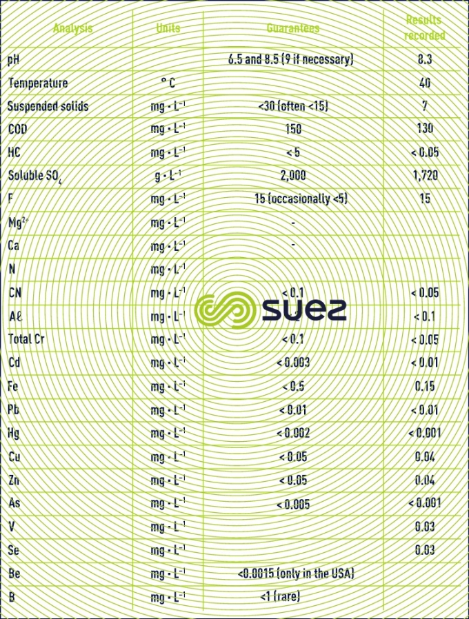
Table 27 details the guarantees normally found as well as the results obtained with one of the plants that is currently operating.
It should also be noted that COD guarantees of the COD < 150 mg · L–1 type are increasingly being demanded. As incoming levels range from 250 to 500, a tertiary treatment will often be required (biological but only for low salinity levels or preferably with activated carbon in view of the low flow rates).
It should be noted that this COD is sometimes due in part to the suspended solids in the effluent. By simply removing these suspended solids, we can achieve less than 150 mg · L–1 at the structure’s outlet.
Finally, we need to bear in mind that, in the case of fluorine, a < 15 mg · L–1 guarantee is achievable by co-precipitating CaF2 with gypsum; however, a < 5 mg · L–1 guarantee is not possible unless F is already below that figure in the raw water. In the most common case where fluorine is higher, tertiary treatment becomes necessary, using aluminium sulfate, for instance.
The FGD treated water discharge standards vary from one country to another, but almost globally we see that these standards are becoming more and more strict, with an increasing number of metals and other parameters being regulated. The discharge standards are becoming particularly difficult to achieve for parameters such as selenium (the selenate species is very difficult to remove by physical-chemical process), mercury, boron, nitrogen species and COD.
We see more and more the implementation of biological treatment for reduction of metals such as selenium, hexavalent chromium, and thallium; also we see the utilization of ion specific ion exchange resins for removal of elements such as boron and mercury. Ultimately, as these regulations become even more strict, the treatment line for FGD wastewater could change from simply physical-chemical treatment to include also either biological treatment or evaporation and/or crystallization (zero-liquid discharge or ZLD).
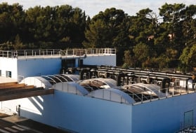
The iBIO system employs two anaerobic reactors, an anaerobic clarifier, and an anaerobic continuous backwash sand filter (photo 19) for the removal of boron and selenium.
Bookmark tool
Click on the bookmark tool, highlight the last read paragraph to continue your reading later
