


wastewater reuse for power plant make-up water
Reading time:In dry regions of the world, industries are increasingly being asked, even compelled, to reduce or even eliminate extraction of any natural surface or groundwaters. Therefore, wastewater reuse and, in most cases, municipal wastewater reuse (see example of Pemex oil industry) becomes a required approach. Industrial wastewaters can also be reused effectively in many cases. This is particularly applicable in the case of new co-generation power stations that often have major industrial clients for their products (steam and electricity) that can in return provide power stations with industrial wastewater, treated to a greater or lesser extent, as a water resource.
A typical example is that of Gregory Power Partners (Corpus Christi, Texas) where a co-generation plant has been constructed. Its main client is an aluminium smelter. This aluminium smelter discharges low saline condensates containing variable and high organic content: TOC of approximately 30 mg·L–1 peaking at 60 which must be reduced to 0.5 ppm in order to satisfy water quality requirements for steam generation in the HRSG units. As there is often a shortfall of condensates, water from the San Patricio river provides the additional quantities required in order to deliver 384 m3·h–1 to the cooling systems and up to 830 m3·h–1 as make-up water for the power station’s boilers.
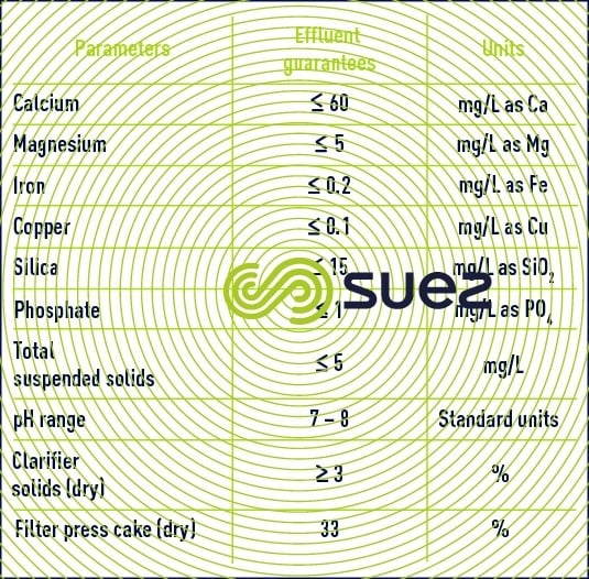
Tables 15 and 16 detail the analysis required; in fact, once the TOC for both sources of condensate (bauxite "digesters" and evaporators) has been stabilised, for 98% of the time, these levels are below 25 and 45 ppm, respectively.
An example of municipal wastewater reuse is that of the Northern California Power Association – Lodi Energy Station’s natural gas-fired power generating station in Lodi, California. The plant has a capacity of 300 MW and is located adjacent to the White Slough Water Pollution Control Facility (WPCF), Photo 20. The power plant requires 1,800 gpm (2.6 MGD) of clarified water.
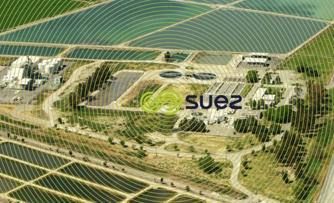

The White Slough WPCF has an average annual flow of 6.3 MGD with a design flow of 8.5 MGD. The wastewater treatment system installed at the Lodi Energy Center generates 1,800 gpm (2.6 MGD) of clarified water using the effluent from the White Slough WPCF. The clarified water is then demineralized with a required flow of 90 gpm for boiler feed water and up to 200 gpm for the plants evaporative cooling system. The Lodi Energy Center also treats around 200 gpm of cooling tower blowdown which is then recycled to the head of the water treatment process or handled by a deep well injection system. The Lodi facility also has a condensate polishing treatment system capable of handling 1310 gpm of condensate.
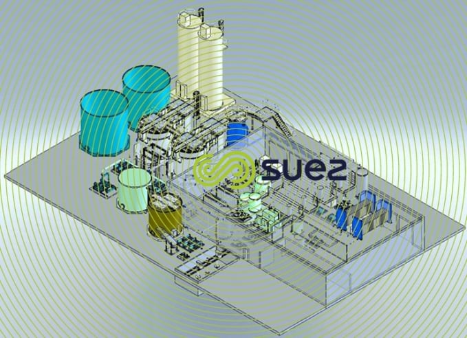
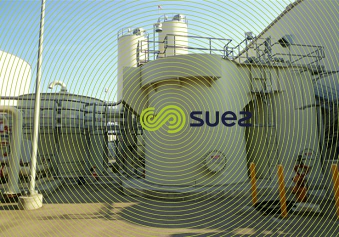
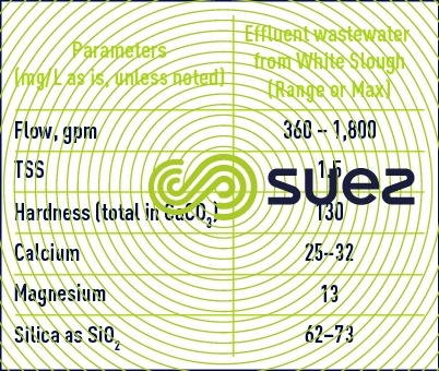
The influent design parameters for the Lodi Energy Center (photo 21), can be found in Table 28. Lime and sodium carbonate are added during the clarification treatment to remove the soluble calcium and magnesium by forming calcium carbonate and magnesium hydroxide, respectively. Magnesium oxide is added to remove silica via adsorption. Polymer is added as a flocculent aid and sulfuric acid is added for pH control. The Densadeg can be seen below in photo 22. The effluent guarantees for the clarified water can be found in table 29. All effluent guarantees were met during performance testing.
For the demineralization treatment system at the Lodi facility two (2) ultrafiltration trains, photo 23, and RO cartridge filters were installed prior to two (2) RO trains and two (2) Electrodeionization trains. The RO system was required to meet a particle removal of ≥ 3 microns to protect the deep well injection system. The condensate polishing system consists of feed water pumps, mixed bed condensate polishers, and a resin fill and storage system.
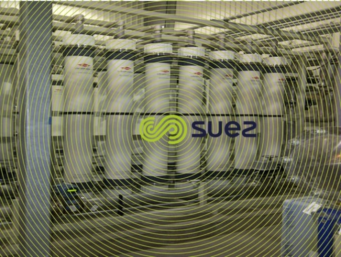
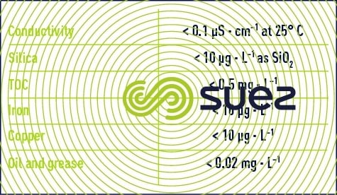
Figure 38 provides the treatment scheme selected (verified using a pilot scheme), constructed and operating continuously since 2000.
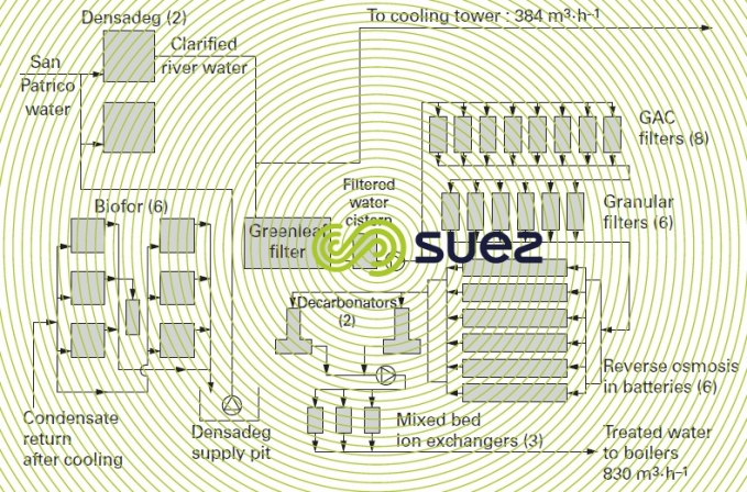
It comprises :
- biological processing using a Biofor
- the water discharged by the Biofor is clarified through two Densadeg,
A polishing-demineralization system is included to treat a portion of the clarified effluent of the mixture and, as shown in figure 38.This system comprises :
- tertiary filtration dual-media through a Greenleaf filter;
- filtration over granular activated carbon granule (protected against the risk of bio-fouling by regular cleaning using live steam (once every 1 or 2 months);
- additional filtration through a twin-layer filter used to remove carbon fines and to achieve an SDI that is compatible with reverse osmosis ;
- reverse osmosis followed by mixed beds complete TOC removal and TDS reduction.
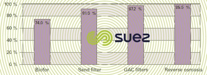
It should be noted that after 18 months of operation, the decision was made to «by-pass» the GAC filtration as part of the operation because it became superfluous, as there were no TOC peaks.
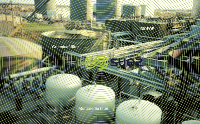
Photo 24 illustrates part of the treatment: Biofor - Greenleaf filter – multimedia filter.
Bookmark tool
Click on the bookmark tool, highlight the last read paragraph to continue your reading later
