


series assembly – desalination membrane discharge
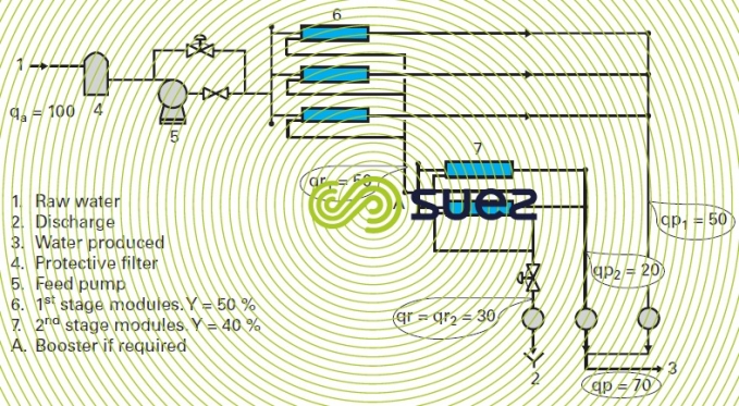
Reading time:The schematic diagram in figure 8 illustrates this type of layout where three groups of first stage modules feed two groups of equivalent modules. We call this a 3-2 series-discharge stage system. In this case, for instance we can achieve an overall 70% recovery by using the first stage at 50% with eight elements in series within the same pressure tube, and a second at 40% with, for instance, seven elements per pressure tube.
Comment: As discussed in the section Membrane separation, from 100 L of pumped water, the first stage will produce 50 L and the second 20 L, i.e. an overall recovery of 70%.

Accordingly, in order to achieve high rates of recovery, we can use three-stage systems such as 4-2-1 or 5-3-2 configurations. Each time, we need to check that the crosswash flow rate for the element that undergoes the worst crosswash (final element in the pressure tube) does in fact receive a flow rate that is higher than the minimum flow rate recommended by the constructor and the first element a flow rate, whether production or crosswash, that is below the maximum permissible flow rate.
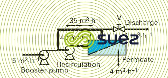
Comment: in the case of small systems (especially pilot systems), the same result can be achieved with one single stage (or even one single element) by recycling part of the concentrate …. See figure 9 where the module is working at Y = 10% (40 m3·h–1 feed, 4 m3·h–1 production) whereas the overall system is working at an 80% recovery (5 m3·h–1 feed, 4 m3·h–1 production) or a discharge concentration subject to a factor of approximately 5. Therefore, this module accurately simulates the concentration conditions applicable to the final element in an industrial installation; however, it will have the hydraulics applicable to the first element. Additionally, it cannot comply with the water’s contact time in the system, an aspect that can be important, especially when scaling inhibitors are used. Furthermore, major water heating during recirculation will often require water temperature regulation.
It should be noted that this principle also applies to MF or UF systems operating in recirculation mode (see section Membrane separation) except that their deconcentration is intermittent (during backwashes) instead of continuous (discharge).
series-discharge assembly with a «booster» between stages
In some cases, especially where a high recovery rate applies, it can be of value to increase the pressure at the second and/or third stages in order to maintain high specific outputs under acceptable hydraulic conditions. This is effected by using booster pumps positioned between each of the stages (see point A in figure 8) that more or less compensate the first stage head loss by increasing the osmotic pressure.
Bookmark tool
Click on the bookmark tool, highlight the last read paragraph to continue your reading later
