


desalination systems (RO, NF)
Reading time:The membrane is always the first item to be selected and this choice will be dictated by the type of separation required (see salt passage (SP) of desalination membranes; the type of module then has to be selected (see section available modules – their geometry) and, finally, the module layout (see the different types of layout (desalination system):
- one or several stages (series-discharge) in order to achieve recovery and, therefore, target water loss;
- one or more passes in order to obtain the quality required when there are no modules capable of producing an adequate discharge.
Then, the system’s major operating parameters must be selected with great care: pressure, recovery, used to optimise system investment and operating costs while complying with :
- each module’s internal hydraulics (minimum and maximum flow rates);
- the non-precipitation of the least soluble salts (or too much cake deposited); this non-precipitation depending on the quality of the water that has been pre-treated if necessary... (see laws detailed in the section chapter Membrane separation).
Finally, we need to ensure that the material selected for all accessories (corrosion-pressure resistance) is appropriate and this also extends to backwash or periodic chemical washing equipment.
All the necessary calculations can be carried out through repeated iterations using the documentation and calculation programs provided by the various suppliers of membranes or water conditioning products (scaling inhibitors, dispersants, biocides …).
As already discussed (see section clarification membranes), UF membranes that have low removal thresholds (< 50 KD) behave in much the same way as desalination membranes when they are used to eliminate and/or concentrate macromolecules.
The first two selection criteria are as follows:
- salt passage that results in the quality of the water produced;
- minimum operating pressure for providing an adequate flow.
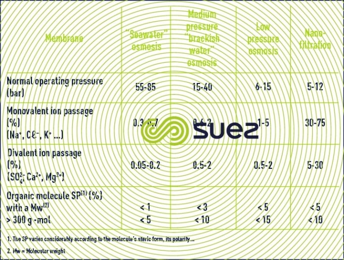
Table 3 summarises the performance levels that can be obtained (salt passage and pressure) with an osmosis unit. Warning : this table is only provided for guidance. In fact:
- progress is ongoing in the field of membrane selectivity;
- and, above all, a precise salt passage can only be established for a given effective trans-membrane pressure (ΔΡ – Δπ) and for a given recovery. Consequently, the figures provided in table 3 will differ from those provided by suppliers whose figures refer to precise “standard” conditions that are not the same as the average installation conditions.
Finally, membrane ageing phenomena generate a declining efficiency that has to be taken into consideration.

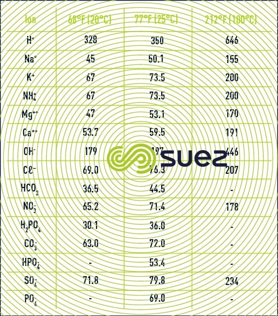
example of how to use the above table:
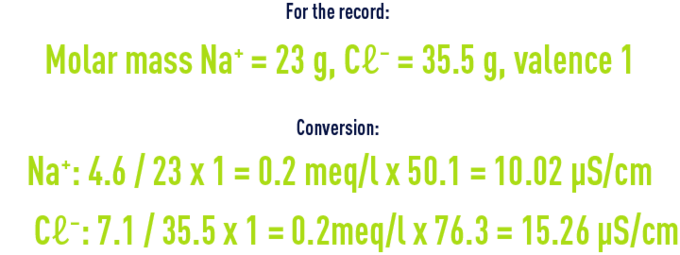
Assumption : osmosed water has a temperature of 25°C and a salinity of 11.7mg/l, composed only of Na ions: 4.6mg/l and Cl ions: 7.1mg/l.


For the record, conductivity values are always given for water temperature at 25°C.
The conductivity meter, resistivity meter measuring devices are equipped with a probe to correct temperature and give standardised values at 25°C in temperature.
Reminder of the conversion of °F into °C -> °C = (°F – 32) / 1.8
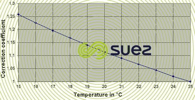
The actual conductivity may be reached at temperatures different from that of 25°C by using the following graph.
for this example:
The conductivity of 25.335µS/cm at 25°C gives 25.335/1,115 = 22.7 µS/cm at 20°C.
selecting module layout and operating parameters
When the membrane type has been selected ( SP ), the module then has to be selected and, as we have already seen, spiral-wound modules must be selected in 95% of cases on financial grounds.
From that point, a number of limitations apply and these have to be satisfied by means of an approach that is roughly sketched out below. First of all, the choice of recovery: we have already seen (see Membrane separation) the fundamental importance of this parameter that governs the entire engineering and economy of a system and that has been summarised in table 5:
The main operating cost is often generated by the energy consumed and, therefore, encourages the use of high recovery levels. However, this only becomes possible by simultaneously satisfying three essential conditions:
- internal hydraulicsthat determine module layout;
- risk of scaling (that depend on the chemistry of the water discharged) … see typical reagents;
- a minimum quality of water to be treated in order to prevent the modules from fouling up too quickly … see flocculation with sludge contact.
scaling risk
Through "construction", exept in very exceptional cases using tubular systems or, at the outside, plate-type systems, it is absolutely inconceivable that there should be any precipitation which would accumulate crystals in a module and would very quickly prevent the water from flowing properly through the spacers. Therefore, we must check that all cation i – anion j couples in the concentration found in the discharge are unable to precipitate and, consequently, that the product of their concentration at the discharge point does not exceed the corresponding salt solubility product ij (ksij) which can be written as follows for a given temperature and pH:
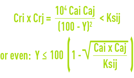
where Cai and Caj are the incoming I ion and j ion concentrations,
Cri and Crj are the discharge I ion and j ion concentrations.
It should be noted that the least soluble salts are the alkaline-earth salts such as CaCO3, CaSO4.2H2O, CaF2, BaSO4, SrSO4, CaHPO4, as well as all metal salts (hydroxides, sulphides, phosphorus …) and silica.
Therefore, an analysis of all these elements and of their potential fluctuations in time must constitute the compulsory basis for any worthwhile project.
When at least one of the couples restricts the target recovery, there remain three possible options:
- either limiting Y by means of the above formula;
- or pre-treating the water in order to reduce the concentration of one or other of the i or j ions, for which purpose, the following methods are routinely used :
- acidification in order to reduce HCO3– ions and, therefore, to limit the danger of any calcium carbonate precipitation;
- softening and/or carbonate removal in order to eliminate Ca2+, Mg2+, Ba2+, Sr2+ ions and certain metals;
- iron removal, manganese removal, silicon removal … (see section the different types of layout (desalination system)).
- or, finally, the use of scaling inhibitors (products similar to those used in boilers and other cooling systems) and that can normally be used to temporarily inhibit precipitation through a threshold effect or by altering the salt’s crystalline structure. However, we still have to check that these products are compatible :
- not only with the membrane and, therefore, specifically formulated;
- but also with all the compounds in the water and with pre-treatment reagents.
It should be noted that, in this context, reverse osmosis has two advantages over thermal desalination:
- reverse osmosis works at normal temperatures (usually Ks drops when T rises with the notable exception of silica)
- and above all the water is only in the system for a short time (a few minutes) unless the plant is shut down.
In order to cope with the latter case, the use of an inhibitor involves an automatic rinsing system (even in the event of a power cut) for replacing module contents with stable water (pre-treated or permeated water): an operation often called flushing.
Suppliers of inhibiting products usually quote a super-saturation that can be obtained using their product (e.g. twice Ks).
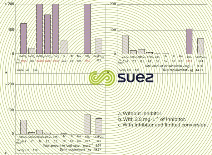
Comment: osmosis plant design software (also known as "projection") combined with an inhibitor product software is used to calculate the discharge solubility for the most common "scaling" salts, with or without an inhibitor.
Figure 12 is a visual representation of the results produced by this type of calculation based on an example where it is clear that, without an inhibitor (figure 12a), CaCO3, BaSO4, SrSO4, CaF2, SiO2 solubility is exceeded; on the other hand, if we add 3.80 mg · L–1 of Permatreat PC 510 (figure 12b), the only remaining risk is that of silica precipitation and this can be resolved through partial silicon removal or more cost-effectively as in this case, by reducing the recovery by a few points, rapidly resulting in a good safety margin (figure 12c).
risk of fouling
Fouling is caused by any particle depositing on the membrane when this particle is not drawn away by the crosswash. When this happens, we see a gradual deposit forming, often known as a "cake" whose resistance to drainage has to be added to that of the membrane, causing a loss of flow. Additionally, by hindering the back diffusion of salts rejected by the membrane, this deposit increases polarisation concentration phenomena. Finally, by obstructing the free areas between the spacers, this deposit induces a head loss in the circulating liquid and the danger that the entire membrane surface area will not be properly irrigated.
main causes of fouling
There are three different types of the main compounds likely to accumulate on the membrane:
colloids in the feed water
The most classic of these are given below:
- surface water silt (often fine clays), possibly fine sand, and micro-algae, even dead;
- grease, hydrocarbons, insoluble polymers, which are to be feared as they can coat membranes with a film that is more or less irreversible and create extremely sudden flow losses.
oxides – hydroxides
These metal sulphides can precipitate on membranes depending on the pH and on concentration level (see scaling mechanism) producing compressible and, therefore, extremely resistant cakes.
biological fouling
Insofar as when micro-organisms (bacteria, fungi, yeasts) are present in the supply water, even in very low numbers, they will accumulate along the membrane in the same way as other colloids. However, if, at the same time, they encounter a concentration of nutrient: BDOC (biodegradable organic carbon), regardless of its origin (natural, pollution, oxidation by-products …), they will proliferate and gradually attach themselves to the membrane via their exo-polymers, creating a biofilm similar to the ones described in attached growths. In addition, this biofilm will include the products already mentioned (oxides, hydroxides, colloids…).
consequences
Regardless of the nature of its compounds, fouling will produce one or more effects:
- an increased head loss. This is often the parameter that will provide a warning;
- an increased salt passage (and possibly an increased polarisation concentration);
- a loss of flow.
In order to react in time, the plant’s results must be monitored regularly in order to pinpoint any such deviations quickly which in turn assumes an interpretation of the raw data provided by instruments. In effect, as already seen, an increased crosswash flow rate caused, for instance, by a deliberate reduction in recovery or by a temperature fluctuation will produce the same effects as excessively high fouling: increased head loss and fluctuating flows. Also, in order to be able to appraise the situation, results first have to be harmonised, i.e. by calculation, basing them on the same pressure, temperature and recovery condition and exclusively using these harmonised results to ascertain if changes to head loss, SP or flow are significant and, in this case, for instance, to decide whether a chemical cleaning campaign should be initiated.
means used to minimise fouling
There are four possible strategies (used singly or in combination) for minimising this fouling:
pre-treatment:
The couple optimum clarification followed by filtration (if necessary over two successive stages), in almost all cases, produce water that is completely colloid-free. This feature can be verified using the FI (fouling index) or SDI (silt density index) test (see section measuring global parameters). In effect, this is the best available reference for ascertaining the danger of module fouling.
Spiral-wound module suppliers recommend using their modules with fouling of less than 4 or 5. However, experience has proven that normal fouling below 3 or better still, below 2.5 with possible peaks of 4 or 5, will be required in order to achieve a system that is easily operated.
It should be noted that there is no universal correlation between turbidity and the FI although experience has shown that an FI <3 usually relates to turbidity below 0.15 NTU, which explains the very particular care that is needed when clarifying water to render it compatible with spiral-would modules. For instance, with surface water (lake or seawater) deemed clean (turbidity < 2 NTU), two filtration stages are often required with coagulation at least upstream from one of these in order to obtain a satisfactory fouling index, without allowing for the fact that if we have to cope with abnormal turbidity peaks, with algal "blooms" or with hydrocarbon inputs … a floatation stage may become compulsory (e.g. Rictor floatation).
Polymers, whose beneficial role was stressed in the section Coagulation-floculation need to be used with care in these cases (choice and amount used) to prevent them from being more or less irreversibly adsorbed by the membranes. Membrane clarification (combined with a settling tank or a flotation unit if necessary) is clearly a possible option (see section desalination membrane application).
A properly designed pre-treatment will always be a key factor for obtaining a reliable system, requiring a minimum of washing and ensuring long osmosis unit service life (6 to 10 years depending on the case). It is also the most delicate issue, calling on the entire expertise of the best professionals (knowledge of the quality of the water encountered and of the best available technologies).
choosing the specific output or flow :
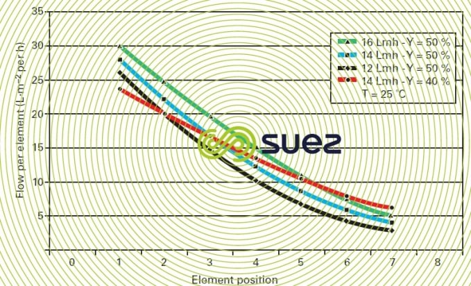
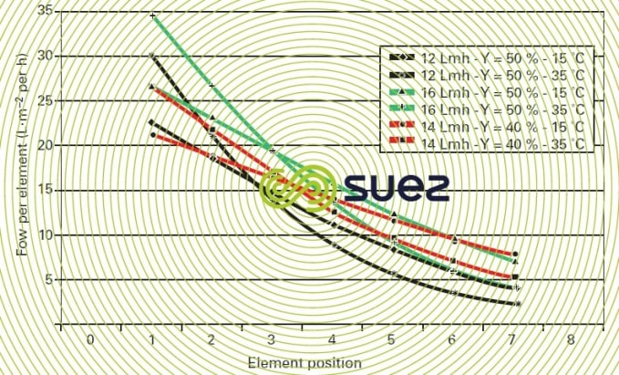
Permeate output per m² of membrane and per hour expressed in (L·m–2·h–1 or even LMH) is also a very important factor. In effect, the higher this output, the greater the quantity of colloids inputted each hour per unit of membrane surface area. This requires the module to be cleaned more frequently. In order to compensate for this, we need either to opt for the most efficient pre-treatment systems, or select low recovery rates in order to have powerful crosswash currents (options that can often prove costly). Conversely, selecting reasonable specific flow rates, especially through the first elements, means that ΔP changes and wash frequencies will be reasonable.
Figures 13 and 14 illustrate the difficult nature of these choices in connection with a seawater system by showing the true flow levels within the same pressure unit (series of seven elements) and e.g. (figure 13) that an average flow of 14 LMH for Y = 50 % does in fact apply to a first element being supplied at 28 LMH and the last at 4 LMH only !
This choice would result in the first element rapidly becoming fouled when the water is not of an excellent quality. The situation improves when we only have a 40% recovery.
Figure 13 also shows the effect of temperature at a constant recovery level and the extremely high risk posed by the recovery – temperature – high flow combination.
- When biofouling can be expected, we either need to try to eliminate all the micro-organisms, a virtually impossible task, or rather, attempt to remove the nutrient source (BDOC) and the food, especially phosphorous. The use of a compatible biocide as shock treatment is also recommended.
Comment: regular rinsing with permeate water that induces osmotic shock constitutes a good solution on high salinity water (> 5 g · L–1).
- A recent development has seen membranes said to be fouling-resistant coming on to the market; this property is usually based on their reduced surface electrical charge, making it less easy for them to "capture" particles. They have initially been successful in the recycling of wastewater (classic or twin-membrane systems, see section desalination membrane application).
chemical washes
Finally, regardless of the care taken with pre-treatment and with good plant design (module layout...), a unit for washing modules at regular intervals is essential. This unit:
- must be connected in succession to each stage of each of the lines making up the system (fixed systems or those that can at least be easily connected);
- must be capable of circulating, at low pressure (the aim is not to percolate through, but rather to crosswash the membranes) the washing solutions selected on the basis of what is known about the compounds that are likely to contribute to scaling (re-dissolution of precipitates) or to fouling (cake that needs to be dispersed) in order to reinstate initial membrane condition.
Major washing products include acids (hydroxide, carbonate dissolution), chelating agents (oxides – hydroxides), surfactant dispersants (dispersing organic or mineral fouling), disinfectants (biofouling) …
In almost all cases, alternating a soaking period (impregnation) with circulation (breaking down and transporting the "cake") will produce the best results. The wash may be long and difficult when major blockage of separation screen channels is allowed to develop, preventing the products from penetrating right into the cake. This may require the wash to be extended from a few hours (2 to 4 hours per product) up to several days. On the other hand, the sooner the problem is detected, the easier the wash.
It should be noted that an inadequate wash must be repeated rapidly most of the time because the matter remaining on the membrane will help crystallisation to start, prevent proper membrane crosswashing and even allow biological recolonisation to start (exopolymers that have not become detached).
At least on the larger systems, an autopsy carried out on one or more modules, either the first element of the first stages (fouling) or a tail-end element from the final stages (scaling) can be informative: it can be used to collect precipitates and/or cake, to analyse these and, therefore, to select more appropriate wash products.
Similarly, a unit capable of testing and then washing several elements will allow these washes to be fine-tuned.


Bookmark tool
Click on the bookmark tool, highlight the last read paragraph to continue your reading later
