


systems using clarification membranes
Reading time:the internal skin modules
In accordance with desalination systems where spiral elements are all interchangeable, external skin clarification membranes (hollow fibre) are currently in the form of modules where both the geometry as well as the membrane material are interchangeable. This contrasts with internal skin clarification membranes where modules marketed by suppliers are incompatible and cannot be changed without reengineering the membrane filtration unit.
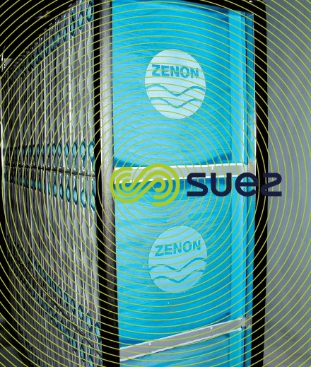
Photo 2 shows the configuration of Pentair module (e.g. pressurised module – internal skin fibres).

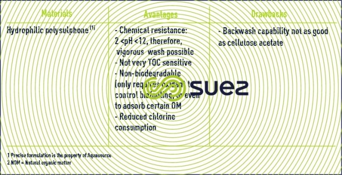
The choice of membrane material will depend on the different criteria summarised in table 7.
These modules are usually assembled :
- on individual skids: a pump, a group of modules and its automated controls, for use in small size plants;
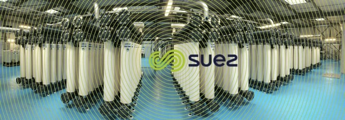
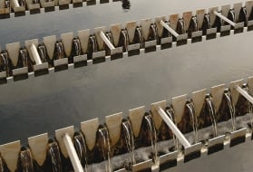
- as a "block" (photo 3): a series of modules with their headers serviced by a pumping system, automated controls, backwash system (as detailed in the schematic diagrams found in the section Membrane separation figures 59 et 60); the target is 100% dead-end operation or, otherwise, continuous tangential operation or only episodic operation (e.g. at turbidity peak times).
submerged membrane system
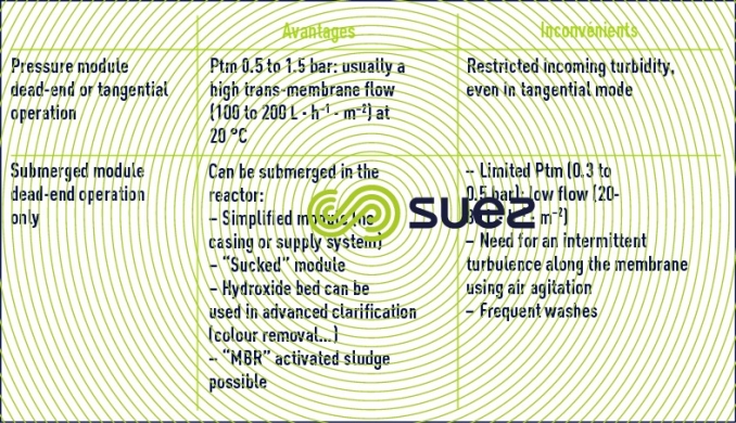
Table 8 summarises the advantages and drawbacks of a submerged membrane compared with a pressure membrane.
Zenon submerged membranes are typical of the options available with this technology.
membrane that can be submerged in the water to be treated or even in the sludge blanket :
Zeeweed series 500 modules. These modules consist of layers of reinforced fibres with resin potted upper sections. These fibres can be assembled in cassettes containing several modules (10, 20, 60) with one single source of feed, a permeate outlet, an air header ... Photo 4 shows a cassette containing 16 (maximum possible is 20) modules in the process of being assembled.
The backwash modes consist of :
- backwashes proper using permeate water which can be chlorinated or acidified if necessary;
- thorough backwashes with a soaking period ranging from a few tens of minutes to 1 or 2 hours in more concentrated solutions. E.g. 200, or even 2,000 ppm Cℓ2, citric acid …;
- "regeneration" type chemical washes carried out either by removing the cassette and soaking it in an ad hoc tank or, in the larger plants, by washing all the cassettes from the same tank at the same time (which supposes the availability of several tanks (line) in parallel or that provisions have been made to shut down the line affected; 8 to 16 hours).
These modules are submerged in the water to be treated but they could equally well be submerged in a "sludge blanket" which can, depending on the applications, be formed by activated sludge (see Ultrafor) or by hydroxides and, occasionally, by PAC (surface water or aquifer containing Fe, Mn, OM). In the latter case, a flocculation tank will be required upstream from the module submersion tank.
membrane that can be submerged in low turbidity water
(reservoir water, thoroughly clarified water, wastewater after secondary clarification, clean seawater …).
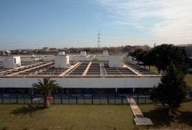
These are also external skin hollow fibre membranes but of a smaller diameter and without any textile reinforcement. They are fixed horizontally in modules assembled on several levels (photo 5). These Zeeweed series 1,000 modules are backwashed using air injected into the base of the system during the backwash only. Thorough backwashes or mini-backwashes can be carried out. The wash water is collected in channels installed above the modules or by draining the tank.
These systems have been designed for large units of more than 500 m3·h–1 and have the advantage of being extremely compact and less expensive; however, they can only be used (see above) on low turbidity water in order to maintain a reasonable washing frequency.
selecting operating parameters
Therefore, the designer is faced with the following main options :
- dead-end or tangential operation (pressure module);
- and above all, the working flow.In fact, this parameter defines the number of modules to be used and also the quantity of matter that accumulates between two backwashes and, consequently, the frequency of these backwashes. However, if it is too high (higher than what is sometimes regarded as the critical flow), there will be flow and permeability drifting that can only be rectified by chemical washes. Consequently, it is of paramount importance that this critical flow be ascertained through experimentation or on a pilot scheme.


Let us not overlook the extremely important effect of temperature which, in surface water for instance, may often fluctuate from a few degrees in winter to 25°C in summer, representing a flow rate differential for a constant TMP (even water viscosity) of more than 35% or even 45%! Therefore, we need to know if requirements remain the same in winter in order to avoid over-designing the plant.
As in the case of reverse osmosis, a thorough knowledge of all the properties of the water to be treated and of their seasonal variations is absolutely essential.
With some low turbidity water that does, however, contain organic matter, even when the cake accumulating on the membrane is very fine, it may not submit to backwashing very well (some authors refer to a "sticky" cake). In such cases, micro-coagulation using between 0.2 and 1.5 ppm of a metallic coagulant (especially FeCℓ3) will markedly improve backwashing capacity and, therefore, the working flow that can be achieved.
If the aim is to remove dissolved organic matter, clarification membranes alone will not be enough (their removal threshold is too high). On the other hand, these membranes do provide an excellent barrier preventing any powdered activated carbon ( PAC ) through, the latter being capable of fixing dissolved organic pollutants such as pesticides and/or products that generate taste. This approach is implemented by injecting PAC immediately upstream from the UF block – known as the Cristal process.
Therefore, the ideal PAC will be made up of grains that are smaller than 10 μm, having very high adsorption kinetics but that will not block the fibres. These grains are injected into the feedwater, if necessary after an initial contact (a few minutes). The carbon accumulates in the recirculation loop from which it is only removed when a backwash takes place. Clearly, if there is either a sludge blanket clarifier (e.g. Pulsator) or a sludge recirculation clarifier (e.g. Densadeg) at the top of the processing line, the carbon that is "saturated" because it is in equilibrium with the water produced by the UF system, will recover its adsorption capacities as soon as it comes into contact with the more concentrated raw water delivered by the clarifier (see sections Adsorption, membrane processes). This type of system, called «Cristal étendu» [extended Cristal] will allow better use to be made of the adsorbent.
Bookmark tool
Click on the bookmark tool, highlight the last read paragraph to continue your reading later
