


desalination membrane application
Reading time:nanofiltration application
As already discussed, nanofiltration will produce:
- very good OM removal (SP < 5%) especially OM made up of MW molecules approximately > 300 g · mol–1, constituting the main natural organic matter (including organic matter that contributes to colour, THM precursors … (see chapters What water should we treat ? and why ? and Drinking water treatment) and also, for instance, 5 to 20% of common pesticides) ;
- more thorough softening in particular in the presence of sulphate ions; salt discharged through Ca and Mg can reach 98% but then we run the risk of remineralising the permeate before it is distributed ;
- partial desalination.
Consequently, nanofiltration finds its major application in the treatment of hard, high salinity, brackish water (1 to 6 g · L–1) that may occasionally contain colour. The archetypal example is the desalination of some extremely extensive Florida aquifers of which more than 300,000 m3·d–1 are processed in this way.
Comment: before the advent of NF, water was decarbonated, filtered, ozonated and then diluted using non-saline surface water.
But these modules have been developed with discharge levels that are:
- always acceptable as far as OM is concerned;
- average with regard to divalent ions (even SP of approximately 30% over Mg SO4);
- low in monovalents, with a view to avoiding any further demineralisation of water that is already "soft".
These modules are of interest with regard to polishing and lightly mineralised but coloured water (see section membrane processes).
Particular applications have recently emerged such as the removal of sulphates or magnesium and, to a lesser extent, calcium from seawater with the following applications:
- systems re-injecting seawater into oil fields when the presence of Sr+ or Ba2+ in the water in these oilfields prohibits the use of sulphates as this would lead to rapid fouling through precipitation pf Sr or Ba, or again, the case of SO42– injection by encouraging the development of sulphur reducing bacteria action, that can enrich the crude produced with sulphides and cause corrosion in tubings and other "pipelines" ;
- if applicable, desalination using MSF seawater distillation (see section multi-stage flash distillation with recirculation). In effect, the main scaling that can be expected from distillation, as the temperature rises, is calcium carbonate followed by calcium sulphate and magnesium hydroxide.
desalination brackish water
As already emphasised (see chapter Water: a fundamental element and What water should we treat ? and why ?), much water is naturally brackish:
- groundwater that has been in contact with saline formations or that are subject to seawater inflow;
- certain special surface water cases including estuaries.
Additionally, much industrial and/or urban effluent for treatment and/or re-use is also brackish.
In all cases, osmosis has to be the desalination tool of choice, leaving only the niche of very low salinity waters (below 200 ppm TDS) to be demineralised to ion exchange system and only leaving the niche of certain light concentrated brackwish waters (< 1,500 ppm) to be partly desalinated (less than 80 % salt eliminated) but where OM or pathogen elimination is not required (see section dialysis membranes) to electrodialysis.
In this context, low pressure membranes constitute the best choice for water with less than approximately 5 g ·L –1 and that are to be rendered potable; medium pressure membranes (15 to 30 bar) are used to process water of up to 15 g · L–1 or water requiring more thorough demineralisation (SP < 1%).
The key problem is that of ensuring that pre-treatment is appropriate to the water quality. This quality may sometimes be stable as in the case of groundwater but often very variable (estuary water or effluent). Only a thorough understanding of all the parameters:
- suspended solids content, colloids;
- level of the various salts or metals that are likely to precipitate;
- concentration and type of organic matter likely to contaminate water …
can be used to ensure that a suitable quality of water is submitted for osmosis via a pre-treatment that can include all water treatment functions and appliances, including biological treatment (iron removal, manganese removal, Biofor for removing residual BOD or nitrogen, this particularly being the case of recycling or re-use lines (see chapters Treating municipal wastewater, Treatment and conditioning of industrial water and Industrial processes and effluent treatment).
Under the section membrane system design we already saw that pre-treated water quality has to be increased to match the increase in the specific flow selected. Therefore, the first elements will be the most stressed. Indeed, it is not unheard of for their specific flow to be 2 to 2.5 times higher than the average flow. This feature can make the use of "fouling resistant" modules in this position an attractive proposition, albeit to the detriment of lower permeability.

seawater desalination
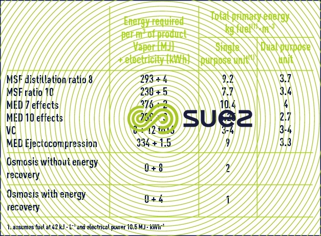
In this constantly developing market, reverse osmosis is by far the least energy-hungry system (table 8) and it is also the one that is the most often capable of converting seawater into drinking water in one single pass. Therefore, it is beginning to compete much more strongly against heat distillation processes. In effect, the latter will only continue to remain cost-effective for high throughputs (> 20,000 m³ per day) and providing that these units can make use of the calories at very low costs, most of the time by extracting them at low temperatures (1 to 3 bar pressures) in electricity – water cogeneration systems (table 9).
competition between distillation/reverse osmosis
In countries where primary energy is expensive, where the new generating stations have not been designed for use in conjunction with distillation and where water salinity is lower than or equal to 41 g · L–1 (Spain, Mediterranean Islands, Israel, United States, Caribbean), the market is almost 100% given over to reverse osmosis with its markedly lower installation and operating costs.
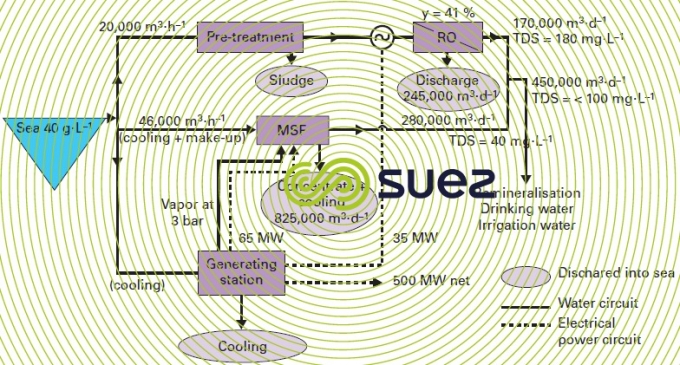
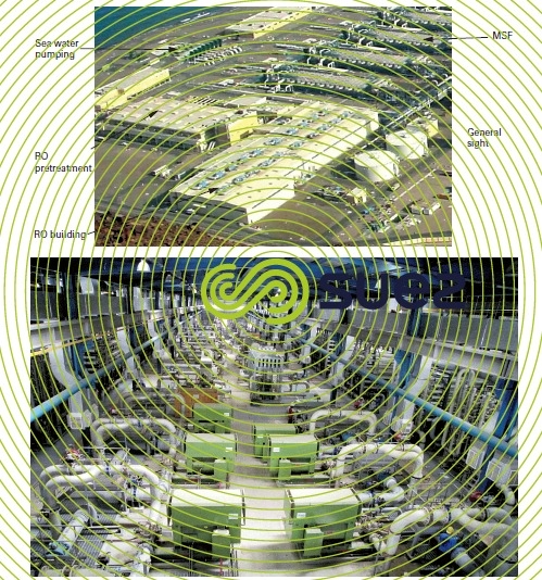
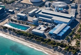
However, even in Middle Eastern markets that had hitherto very much favoured distillation systems that were all connected to generating stations … osmosis has made a very noticeable breakthrough (see Doosan – degremont® plant in Fujairah: 455,000 m³ per day where 37% of the water is supplied by reverse osmosis and 63% by MSF units – figure 16).
In effect, coupling distillation with electricity generation has the drawback of being extremely inflexible, water being produced proportionally to the energy demand when energy demand and water demand curves have no reason for being in phase with each other … On the other hand, a hybrid system, i.e. combining membranes and thermal processes can:
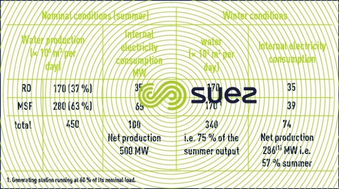
- during low electricity demand periods, produce a maximum amount of water via reverse osmosis, supporting electricity production and, therefore, enabling the latter to keep costs down (table 10);
- during high electricity demand periods, when exceptional peaks occur, osmosis can be shut down (water can be stored to meet demand).
Many technical-financial studies have demonstrated that, for oil producing countries, the optimum m³ heat to m³ osmosis ratio varies between 3-70 and 70-30 depending on the case, especially as a function of the number of thousands of m³ of water that needs to be produced per MW electricity and of energy costs.
design of a desalination unit using reverse osmosis
water intake
The following can be considered:
- either coastal wells or infiltration galleries, ideal solutions for small and medium size plants (<20,000 m³ per day) providing that comprehensive data is available on local geology (first 25 to 30 metres). One or more exploratory wells can often prove useful in order to ascertain the aquifer’s permeability (number and position and wells to be sunk) and its replenishment system (seawater only or a mixture of seawater and local fresh water …). For higher outputs, the number of wells to be sunk, their maintenance and the connecting pipeline system can generally be too expensive.
- or open extraction, but in this case, provisions have to be made for extraction structures that are quite high in relation to the seabed (> 4 m) to avoid drawing up sand, silt, micro-algae lifted through wave effect and sufficiently deep to avoid, whenever possible, the first 5 metres down from the surface and, even better, the first 10 metres in order to limit (even in the event of "rough" seas):
- floating debris, especially hydrocarbon types (degassing, port areas, oil drilling platforms …);
- the better "lit" zones and, therefore, those that are the most "productive" (see phyto and zooplankton).
When the ideal extraction point position is not feasible, grit removal has to be included in order to avoid sludging up and erosion of pre-treatment equipment or "dams" to hold back floating matter.
A study of local currents can be very useful for positioning the water extraction point away from various local pollution outflows (port, UWW or IWW discharge) and also away from the plant’s brackish water outflow.
pre-treatment
Depending on suspended solids loading (colloids) and on the nature of these suspended solids (silt, micro-sand or plankton, provisions must be made for a pre-treatment capable of thoroughly removing them and thus producing a pre-treated water with a fouling index of less than 2.5 and peaks of between 3 and 4. Salinity only has a slight effect on clarification techniques and, therefore, the prevailing techniques used on surface water will apply (see section Coagulation-floculation, Sedimentation, Flotation or Filtration).
Therefore, depending on the type of outlet, the following must be considered:
- coastal wells: in view of the high quality required, the following will suffice:
- either two cartridge filters in series, usually 20 or 50 μm cartridges in series followed by five 1 μm cartridges ;
- or coagulation over a filter followed by a 5 μm cartridge if there is a possibility of micro sand or silt being drawn up.
It is possible that, in the case of deep wells (>30 m), water of an excellent physical quality (FI <1) will be obtained but containing H2S (reducing aquifer). In this case, it is absolutely essential that any air intake be avoided (well head, pump(s)) failing which, sulphide oxidation will produce colloidal sulphur that only coagulates with difficulty and that is extremely "sticky" (H2S passing through the membrane will be stripped on the permeate).
- open extraction: in this case, depending on locations, currents, plankton production, pollution .... we can be facing highly variable water:
- suspended solids < 1 to > 100 mg · L–1;
- FI from 2 more than 35% per minute;
- algae from 10 to 105 cells · mL–1;
- TOC organic matter from 1 to 10 mg · L–1;
and, therefore, depending on the case (going from the simplest to the most complicated) the following provisions will have to be made:
- coagulation over filter at optimum pH (often between 6 and 7.2). In general, a two- or three-layer filter will be needed in order to obtain sufficiently long cycles (always allow a maturation period with discharge to the drains – see filtration through a granular bed). The use of a pressure filter provides greater flexibility when choosing the coagulant(s) ;
- coagulation and two filters in series can also be used on the second of the fine media (⩽ 0,3 mm) ;
- coagulation-clarification followed by two filtrations (for the most difficult cases experienced to date). The clarifier selected will depend on the suspended solids present . However, in most cases, Aquadaf rapid flotation constitutes the best compromise. In effect, this system provides an excellent barrier against planktonic invasions and hydrocarbon peaks (please note membrane supplier zero tolerance to the latter).
As in the case of freshwater, the amounts of reagents, the optimum filtration rate and the cycle duration will depend on the nature of the pollution present. Therefore, in difficult cases, we recommend a pilot test (see example given in the section Pilot tests) or at least treatment feasibility testing on site.
In all cases a 3 to 5 μm cartridge safety filter must be included.
Furthermore, in the previous paragraph, we saw that clarification membranes either used direct or after micro-coagulation, will ensure impeccable water physical quality and, consequently, maximum osmosis membrane service life and specific outputs. Therefore, they appear to offer excellent safeguards but still have to demonstrate their effectiveness on certain organic macro-molecules and their service life span in this environment.
Good pre-treatment providing a low fouling index, something that is always essential, may be enough. Nevertheless, pre-treatment will not guarantee that there will be no biofouling. In fact, biofouling is the main problem facing operators, knowing that:
- this problem is usually avoided in plants fed by properly sunk coastal wells, i.e. where there is no danger of contamination at the wellhead; indeed, in this case, water contains very few bacteria, little OM and nutrients;
- on the other hand, with the conventional water extraction point, water disinfection (chlorination at the extraction point, maintaining a residue during pre-treatment) is a double-edged weapon. In effect, frequently useful for preventing water extraction points from being invaded by molluscs (mussels, barnacles …) and for restricting the growth of bacteria on filtration media, chlorination has the major inconvenience of rendering some of the seawater’s natural organic matter biodegradable (especially humic acids that are naturally non-biodegradable). This biodegradable fraction that is concentrated along the entire membrane, enables a biofilm to develop rapidly, especially when the temperature is high (> 15 °C).
Therefore, in most cases, continuous pre-oxidation has to be avoided and replaced by shock disinfection (followed by dechlorination at module inlets), using, from time to time, as necessary, specific biocides with a view to ensuring that the modules remain clean.
Comment: in warm water, the same precautions apply in front of a clarification membrane.
It should be noted that supplementary methods used to avoid bacteria invasions must be recommended:
- the use, from time to time, of chlorinated water as washing water for filtration media;
- washing filters with the discharge from osmosis, creating osmotic shocks that have a biocide effect;
- flushing with permeate water inducing the same effect at the modules (once or twice a week).
the osmosis block
These systems are basically simple because they are often constructed as a single stage (Y= 35 to 50%) depending on salinity and temperature, and must be designed so that:
- all their components (pumps, pipelines, taps and valves, instruments …) withstand the corroding effect of seawater;
- in the event of a shutdown (whether or not scheduled), flushing with permeate water will avoid direct osmosis phenomena in the modules and corrosion of stainless steel pipelines and valves … caused by stagnant water;
- each block or part thereof can be connected to a central cleaning unit for the purpose of chemical cleansing which, in any event, remains essential from time to time (frequency depending mainly of pre-treatment effectiveness and the flow selected).
These washes must be initiated as already discussed under desalination systems (RO, NF) while monitoring:
- membrane permeability (flow rate corrected for pressure and temperature);
- the module’s head loss (or rather that of the series of six to eight elements housed in the same pressure unit);
- their salt passage.
Typically, any loss greater than 10-15% of permeability or any increase of more than 20 to 30% over the initial ΔP or yet again any increase of more than 15-20% of the SP implies that the appropriate wash be carried out, failing which it may become impossible to reinstate module performance. It should be noted that this regular monitoring of a plant requires quality instrumentation that is properly maintained, as well as software that can be used to harmonise and present results (curves …) in order to assist with the decision-making process.
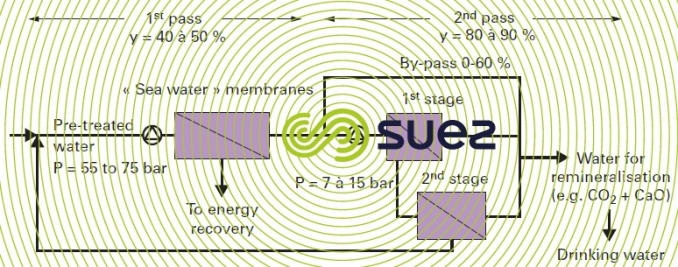
It should be noted that on the most heavily saline seawater (> 40 g · L–1), or when better water quality is sought, e.g. < 200 mg · L–1TDS or when checking for individual elements such as boron (below 1 or even 0.3 ppm): a second stage will be required in the production sequence. This second stage, Often referred to as a second pass, comprises low or medium pressure membranes (see second stage) that re-processes all or part of the permeate output from the first stage of osmosis according to the schematic diagram given below (figure 17). It should be noted that the discharge from the second stage is far less saline than seawater and it is returned to the inlet (no water loss and, therefore, there is no need to allow for any increase in the flow rate to be pre-treated).
special case: removal of boron
Osmosis membranes only thoroughly eliminate ions. However, below pH 9, the curves shown in figure 28 of characteristics solution constants), show that, at 20°C, boric acid, H3BO3, only dissociates very slightly. This dissociation is temperature-related (it decreases as T falls). Thus, for a pH ~ 7.5, seawater membranes will only remove approximately 75 to 90% of B whereas second pass low pressure membranes only achieve approximately 50%-60%..
Overall, if, at a temperature below 25°C in the case of water from the Atlantic Ocean or the Mediterranean Sea with a 36-40 g · L–1 salinity and approximately 4.5-5 mg · L–1 of B, single pass desalination would be enough to meet European standards requirements (currently 1 mg · L–1 B) and, conversely, if higher salinity water (42- 45 g · L–1) has to be desalted, containing over 5 mg · L–1 of B and/or warmer (30 or even 37°C in the Gulf) in order to satisfy WHO recommendations (< 0.5 ppm B), not only do we have to use a system comprising a minimum of two passes (without by-pass) but we also have to alter the pH on the second pass and raise it above 10. In this case and, even allowing for the fact that water produced by the first pass is not very hard (Ca < 4 mg · L–1, Mg < 15 mg · L–1), we still need to use specific anti-scaling products (beware of high pH values: to date, 11 in the discharge) in order to prevent any CaCO3 and Mg(OH)2 precipitation (maximum possible recovery from the second pass is conditional on the inhibitor selected and on the amount used).
The recognised alternative consists in fixing the permeate’s boron on a specific adsorbant resin regenerated using sodium hydroxide followed by acid. The decision regarding a second pass at a high pH or using resin can only be made after undertaking a financial comparison; a combination of both may even be considered in the most problematic cases.
energy recovery systems
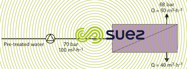
If we use the simplest system (figure 18): a high pressure pump, a single stage membrane system and a 40% recovery, we obtain extremely high specific consumption levels (approximately 6 to 7 kWh · m–3 produced) whereas the discharge valve must release 60% of the feed flow pressure with a pressure equal to the feed pressure minus the pressure loss of the modules (1 to 2 bar).
Also, the concept of "turbining" the discharge in order to recover its energy emerged very quickly and has now become a cost-effective option for plants of any size.
There are several systems available on the market and they can be divided into two major groups:
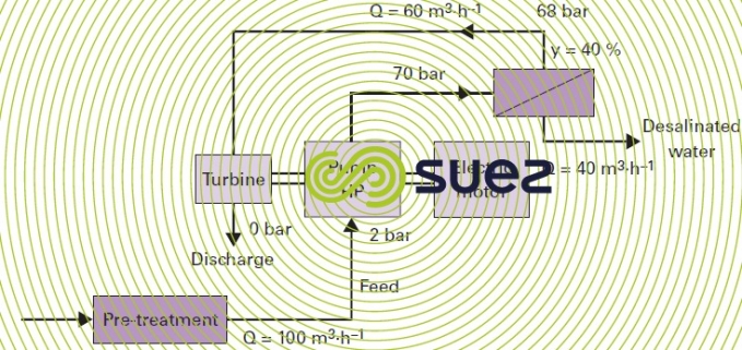
- Pelton type turbine that recovers energy from the discharge by "re-injecting" it at the HP pump shaft, allowing the motor to shed its load as soon as brine has been produced.
Comment: automatic start-up and shutdown procedures must be discussed with the constructor.
With this type of system (figure 19), consumption in the case in point will drop to approximately 3 kWh · m–3 if the high pressure pump selected is more than 85% efficient and if the single pass system is used.
Comment: other, less efficient types of turbine are not used with the larger units.
In this case : the overall system (pre-treatment, pumping at sea, delivery of water produced) will consume approximately 4-4.5 kWh · m–3
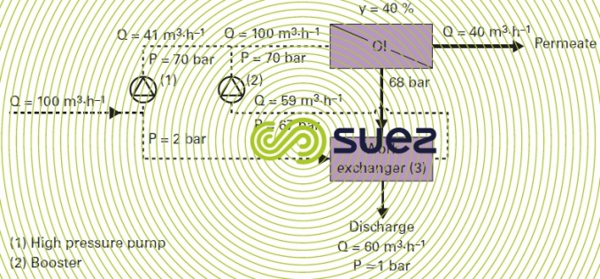
- system called work exchanger (figure 20) that recovers energy from the discharge in order to directly pressurise the same volume of pre-treated water to a pressure of a few bar below the feed pressure (module and exchanger head loss (3)). In this case, the high pressure pump (1), to within 1% or 2% (internal leak in the exchanger system) will only pump at a rate equal to the permeate output, or 41 m3·h–1 in the example used and illustrated by figure 20. A booster (2) makes up the aforementioned head losses (3 bar). These systems (3) (free-piston linear or rotary) are more efficient (94-97%) than centrifugal pumps. Accordingly, we have demonstrated that a plant working up to its design point with 36 g · L–1 seawater can run on less than 2 kWh · m–3 produced.
In general, savings achieved compared with the Pelton turbine come to 0.5-0.8 kWh · m–3 and systems can be produced where the overall consumption is 3.2 to 4.0 kWh · m–3 produced.
Comment: A second complete pass (100%) will consume approximately 0.5 kWhh · m–3 that has to be added to the figures quoted above.

Bookmark tool
Click on the bookmark tool, highlight the last read paragraph to continue your reading later
