


filtration through a granular bed
Reading time:Please refer to chapter Filters for a description of the technologies used in these filters; this only addresses parameters that have an impact on filtration.
The water to be filtered percolates through a filter bed made up of one or more types of granular materials; the properties of these materials and the bed depth must be adjusted according to the water to be treated and the type of filter selected. Suspended solids are held back in inter-granular spaces, throughout most of the bed’s depth.
porous media
physical properties
A material is identified by a range of parameters. Please refer to the section Granular and powdered materials for the different measurement protocols that apply :
- granulometry defined by the effective size (ES) and uniformity coefficient (UC) pair:
- grain shape: aangular (crushed matter) or round (river or sea sand) or more or less flat (see measuring the flattening coefficient). This grain shape is important: thus, we can obtain similar filtered water quality using an angular matter having an effective size that is lower than for the round grain matter; however, for the same granulometry, the rise in head loss will be lower for angular grains than for round grains; in effect, and angular grain bed’s porosity will be higher because, contrary to expectations, this type of grain does not interlock as easily as round grains and leave larger passage sections;
- friability which allows to select materials that are likely to be used for filtration purposes without the danger of wash operations producing fines. A material that is too friable must be avoided, especially in a downward operating filter and where the wash ends with a water only expansion phase since the fines formed will accumulate on the surface and block the fouling;
- loss to acid: it is obvious that major losses to acid are not acceptable when the water is likely to contain aggressive carbon dioxide or any mineral acidity;
- the grains’ density constituting the filtration medium related to their minimum fluidisation velocities;
- apparent densities (bulk) in air and in water
Other properties that are inherent to adsorbant materials such as activated car-bon and have also been addressed in Granular and powdered materials.
nature of the porous medium
Quartziferous sand was one of the first materials to be used in filtration and it is still the basic material used for most filters today.
Some filters use a combination of several materials (multi-medium filters). Sand can also be used in conjunction with anthracite, pumice, garnet, schists that are more or less porous – providing that these materials have low friability and loss to acid.
Filtration can take place through sufficiently resistant granular activated carbon: during the first stage of filtration with a view to removing residual floc and to using adsorption to fight against pollution; or even better, during the second stage of filtration for finishing only or for dechlorination.
For some treatments where an enhanced biological action is needed, the use of materials having a high specific surface area can be of interest, such as biolites, expanded schist, Pozzolana….
Anthracite or marble can be used instead of sand when it is essential that no trace of silica be left in some industrial treatments (e.g. condensate treatment) or when a supply is easier to obtain (and, in the case of marble, when the water is not at all aggressive).
control and optimisation
monitoring a filtration cycle
Three inspection methods are normally used to monitor filter operation.
measurement of changes in filtered water quality
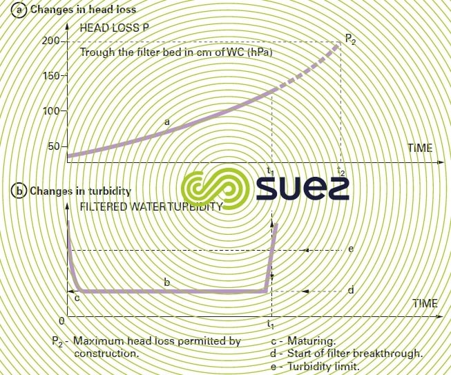
Curve b in figure 39 illustrates the changes in filtrate turbidity and establishes characteristic filter operating period :
c = maturation period,
b = normal operation period,
d = filter begins to break through,
e = acceptable turbidity limit; filtered water turbidity will reach this figure for a time t1 when the cycle must be stopped.
measurement of and changes in total pressure drops
The graph showing changes in head loss P is plotted as a function of time (curve in figure 39). Through construction, there will be a maximum head loss that the filter cannot exceed: e.g. P2 = 200 hPa (2.00 m of WC). This head loss will be achieved after a time t2.

pressure graphs (triangular diagram)
Section a of figure 40 represents an open gravity filter having a sand depth equal to BD and a water depth above the medium, AB. The right hand graph has the pressure sampling heights A, B, C and D above the filter floor D along the Y-axis and the pressures shown as water depth along the X-axis, both being to the same scale. Thus, at point b on the filter, located at the top of the filter bed, pressure will always be equal to the water depth AB, shown as B’b. At point C on the filter bed, when the filter is not working, the pressure will be equal to AC, shown as C’c0 ; similarly, the static pressure at floor level will be equal to AD and shown as D’d. All points representing static pressure at the different levels in the filter can be found on the 45° straight line, A’d. Atmospheric pressure applies at all points along the straight line A’D’.
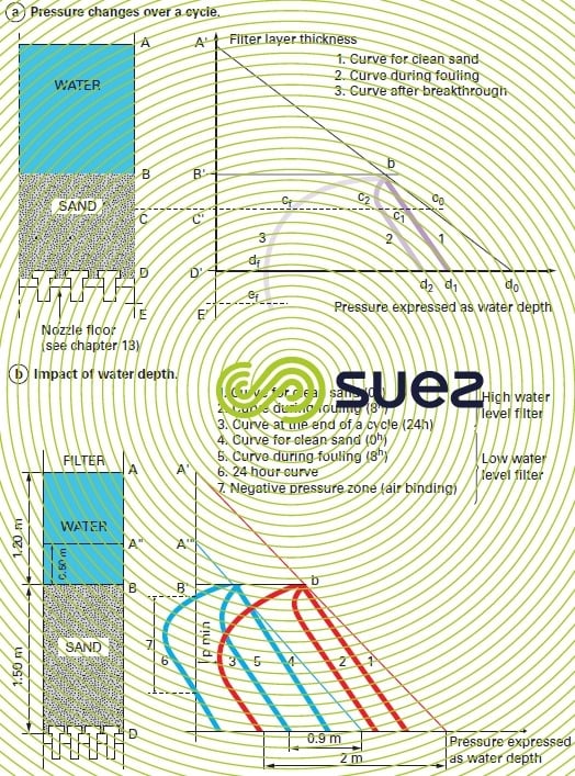
Once the filter has been commissioned and using clean, homogenous sand, according to Darcy’s law, the head loss will be proportional to the depth of the sand and to the flow rate, deemed constant for the purpose of this analysis. Pressure at point C of the filter becomes equal to C’c1, the cc1 value representing the sand head loss between points B and C; similarly, at floor level, the pressure at D becomes equal to D’d1, the head loss through the clean sand being dd1. The bc1d1 line will be a straight line because cc1 and dd1 are proportional to the sand depth (Darcy).
When the sand has completed its ripening period, pressure readings C’c2, D’d2 at the different levels in the sand will provide curve bc2d2 which is representative of the pressures in the filter; it has a curvilinear section (bc2) which refers to the fouled layer, and a linear section (c2d2) which is parallel to straight line bd1 and representative of the head loss through the part of the filter that has stayed clean. The figurative point c2 at the start of the linear pressure drop indicates level C reached by the impurities screened out in the sand. Therefore, point c2 is characteristic of depth BC of the «filtration front» at the time considered.
The shift in point c2 during the fouling process represents the filtration front advance (curve 3). In figure 39a where the filter is no longer delivering clean water when the maximum pressure drop P2 is reached, the curve representing the pressures at the different points of the filter is provided by bcfdfef in figure 40a: it reaches the floor without going through any linear section, i.e. the filtration front has moved beyond the floor and the filter has already broken through (t2 > t1).
If we had used a filter having a greater depth of sand, the curve representing the pressure at the various points in the filter for the maximum available pressure drop would have become linear at point ef: from this, we can deduce the minimum extra depth of sand DE that would have had to be added to obtain t1 = t2 (figure 40a).
Experience has shown that the values of t1 for the different sand depths defined are almost proportional to the corresponding thicknesses.
surface fouling and in-depth fouling
Figures 39 and 40a illustrate a case of in-depth fouling (fouling which, in this case, even goes beyond the lower limit of the filtration layer, indicating a breakthrough phenomenon).
On the other hand, curve 6 in section b of figure 40 illustrates a surface fouling case. This phenomenon can be induced by filtering floc that creates high levels of fouling. It can also be caused by unsuitable material (too fine). Zone 7 is the focus for a negative pressure that can result in degassing, thus reducing porosity ε (see fundamental equations) and generating an additional pressure drop that will shorten the filtration cycle even though part of the filter bed is not being used. The water depth above the sand also has an effect (Filtration).
The optimum scenario consists in attempting to use almost all the filtration layer, but without breakthrough (curve 3 in section b of figure 40).
optimised operation
In water coagulated using a metal salt, t1 and t2 are provided by empirical formulae, indicating the variations in t1 and t2 based on construction and operating characteristics :
- t1 = a·v–0.95·K0.75·D–0.45·L0.95·V–1.85;
- t2 = b·v–0.75·K–0.7·D1.5·P0.9·V–0.65
where :
D: effective size of the material,
L. layer depth,
P: available pressure drop gain (to achieve P2),
V: filtration velocity,
K: cohesion coefficient for the floc held back (see section treatability tests),
v : volume of flocculated suspended solids in the water to be filtered (after 24 hours sedimentation).
a and b are experimental coefficients. Based on one single filtration test, these formulae can be used to calculate the different times t1 and t2 applicable to various operating conditions.
In order to maintain an acceptable quality of filtered water, the filter must reach is head loss P2 at time (t2) before breaking through at time (t1), i.e. t1 > t2. However, in order to optimise cost-effectiveness, it is advisable for the t1 and t2 differential to be low and, therefore, for t1/t2 to be slightly greater than 1; however, if we divide t1 by t2 we obtain :


Thus we can see that for a given bed depth, the effective size of the filtering material and the cohesion of the floc held back constitute essential parameters for t1/t2 variation as they are allocated the highest exponents.
a filters maximum retention capacity
Suspended solids will lodge themselves between the filtration material grains. As sufficient passage must always be allowed for the water to flow, it is unreasonable to expect to fill more than one quarter of the total volume of spaces within the material.
In a 1 m³ volume of material that has an acceptable uniformity coefficient (< 1.5), there will be approximately 450 litres of empty spaces, irrespective of granulometry; thus, the volume that can be occupied by the particles to be held back will be equal to approximately 100 litres, provided that the effective size of the filtration material and the head loss set by construction are compatible with the nature of these particles.
When using an open gravity filter and when the suspended solids to be held back have a hydroxide floc base, this floc’s dry matter content (i.e. the sludge compressed in the interstices of the matter) will not exceed 10 g · L–1 so that the amount that can be eliminated per m³ of filtration material will be approximately 1 kg (100 L ×10 g · L–1 = 1,000 g).
This figure rises when the floc is laden with dense mineral matter (clays, calcium carbonate). In sludge containing 60 g · L–1 of dry matter, this figure can reach: 100 × 60 = 6,000 g.
For example, a 1 m layer depth filter operating at a rate of 10 m · h–1, that needs to be washed every 8 hours (80 m³ of water per m³ of filter bed between two washes), cannot accept more than 1 000/80 = 12,5 mg · L–1 of flocculated suspended solids or more than 6 000/80 = 75 mg · L–1 of dense mineral suspended solids.
An intermediate value will apply to suspended solids in rivers, in direct filtration applications.
In pressurised filtration (e.g. seawater or industrial liquid filtration), the layer depth can reach 2 m and the head loss 0.5 or even 2 bar. In laden water, the filter can hold back amounts of matter of up to :
- CaCO3: 4 to 15 kg per m2 of filtration area;
- oily sands: 10 to 25 kg;
- scale: 20 to 100 kg.
These magnitudes can be used to evaluate the maximum content in matter that has to be screened out and that is acceptable in raw water fed to a filter when we have established its filtration rate and the minimum cycle duration between two washes. Conversely, it is possible to deduce the wash frequency that will apply to a given filtration rate and to a given quality of water to be filtered.
choosing a filter bed
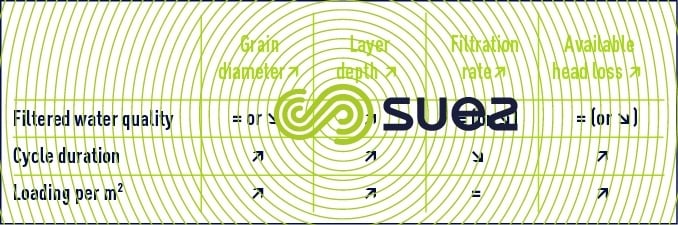
This choice will depend on the nature of the water to be filtered (raw water direct filtration, clarified water filtration, secondary or tertiary wastewater biological filtration) and on target water quality. The choice will also depend on the filter used (pressure filter or open gravity filter) and on the available pressure drop. Table 13 recaps in a summary way the most frequently observed effect of the various parameters on the quality of water and on cycle duration.
Filtration usually takes place downwards in most cases. Depending on the type of wash used (see Filtration) there will be two types of filtration applicable to a range of different materials and/or granulometry.
filtration through a layer of homogenous material (usually sand)
Air and water washes are carried out simultaneously, without any bed expansion. The result is a perfectly homogenous filter bed: filter matter granulometry remains identical at the base and at the top of the filter layer. The filtration front gradually becomes established during the cycle and advances at a regular rate, making filtration cycle control easy. In the filter layer, pressure curve changes are illustrated by curves 1, 2, 3 and part b of figure 40 (in-depth fouling).
This figure also illustrates the impact made by the water depth over the medium: a first type of filter (curves 1-2-3) with 1.2 m of water over the sand will allow, in order to maintain a minimum positive pressure (see p min. curve 3) 2 m of head of fouling whereas a second type of filter (curves 4-5-6) with 0.5 m of water, will only allow 0.9 m of head of fouling (and, therefore, a far shorter cycle: approximately 8 hours instead of 24 as indicated in the present example). If, in the latter example, we attempt to push fouling even further, the curve that represents in-depth pressure will partly move to the other side of the axis that represents atmospheric pressure (curve 6), the relevant part of the filter bed will be subject to negative pressure (see zone 7) and "air binding" will then develop in this bed.
Note: a water wash only with fluidisation will cause the matter to be graded (fines going to the top) and leadto short cycles (surface fouling as illustrated by curve 6).
filtration through several superimposed layers (dual medium or multi-medium)
In order to encourage impurities to penetrate throughout the filter depth, part of the sand is replaced with a layer of lighter matter (usually anthracite) that has a larger effective size than the sand constituting the lower layer; this layer is used for finishing and security purposes. Care must be taken when selecting the granulometry for each of these layers; in effect, it must be possible to expand them both in much the same way using the same wash water output, in order to regrade these layers upon completion of each wash before they are returned to filtration mode.
This arrangement (its design goes back to the 19th century) is used to ensure a better distribution of suspended solids: the coarsest of these are screened out in the upper, large granulometry, layer and this allows us to increase the filter water output per cycle, especially in the case of water containing very heterogeneous suspended solids (typical of direct filtration).
Filtration can also be carried out through three or more layers (e.g. anthracite or pumice, sand and garnet) thus enabling us to increase the suspended solids storage capacity in the upper layers and to improve the quality of the filtrate. However, this requires an extremely meticulous choice of materials and of washing velocity.
washing the filter medium
Washing constitutes an extremely important operation: poor washing will quickly cause some zones to become permanently fouled, only providing a reduced pathway for water; this means that the head loss will increase faster, filtration takes place faster, less effectively and locally ("creation of preferential flow channels").
The filter matter is washed using a water current that circulates from the bottom upwards and that is evenly distributed over the entire filter floor surface area. The purpose of this water current is to detach impurities (to this end, the matter must receive enough energy) before drawing them off into a discharge trough. Several methods are used.
water-only wash for expansion purposes (with surface wash)
We need to use a water flow rate that is high enough to fluidise the filter matter (see Fluidisation), and this assumes that its apparent volume increases by at least 20%.
Given the fact that water viscosity will change with temperature, in some cases, it is advisable to include a system for measuring and adjusting the wash water flow rate in order to ensure that the expansion rate remains within the requisite range throughout all seasons.
The expansion layer will be the source of convection currents, the filter matter circulating downwards in some zones and upwards in adjacent zones; this circulation mixes the matter and encourages the suspended solids that have accumulated in the filter to become detached.
On the other hand, fragments of the compact sludge layer (that tends to form a crust on the surface of the filter matter) can be drawn away into the depths and, under the effect of eddy currents, form large, hard mud-balls.This tendency can be overcome by using powerful pressurised water jets to break up the surface crust; these jets are delivered by fixed or rotating nozzles (surface washers).
This method of washing requires many precautions and the filter matter expansion also has to be measured. Its most serious defect is that it results in the material undergoing granulometric grading, concentrating the fines on the surface; as already discussed (figure 40), this does not encourage lengthy cycles; furthermore, water finishing is less satisfactory, being that the coarser grains falling to the bottom of the filter.
expansion-free wash (simultaneous air and water wash)
A second method, widely used by SUEZ since the 1950’s, consists in using a low water return flow, which is not enough to cause the sand to expand but that will agitate it very vigorously while pressurised air is being injected at the same time. As the sand is no longer expanded, it is not graded and, as the surface crust is totally destroyed by the air, mud-balls cannot form; in fact, they are totally inexistant with this wash method.
- The main wash period is the simultaneous air and water injection phase (the blowing phase). In effect, it is during this period that the energy received by the material is at its most powerful. The minimum water velocity required for an effective wash and the maximum value that must not be exceeded in order to avoid any loss of the filter matter will depend on both this matter and the filter technology used. This velocity will generally be between 5 and 15 m · h–1. The air velocity, which determines the washing energy, will most frequently be between 40 and 60 m · h–1.
- When the impurities have become detached from the filter matter and collected in the layer of water that lies between the filter matter and the discharge trough, this layer of sludge-laden water must be "rinsed", i.e. replaced with clean water. This phase is carried out using water only at a velocity of 15-20 m · h–1. Water consumption during this phase can be reduced by crosswashing the filter surface using a horizontal current of raw water or clarified water in conjunction with the return water (see aquazur sand filters).
successive water and air washes
This type of wash is used when the size and/or density of the filter matter does not allow an air wash to be carried out simultaneously with a water wash without running the risk of material that is fine or not very dense being drawn away to the drains (Note: when the air bubbles attach themselves to the material, this can mean that the less dense materials will actually undergo flotation); this applies to a filter made up of fine sand (ES < 0.5 mm) or low density materials (anthracite, pumice, activated carbon, biolite), a fortiori a combination of these materials (multi-medium filters). During the first wash phase, air is used on its own to separate the impurities screened out from the filter matter.
During a second phase, return water, delivered at a high flow rate, expands the filter material(s) and enables the the separation of impurities from the bed during the first phase to be extracted from the bed and eliminated. Also, this expansion, when it is adequate (> 20%) will ensure the regrading of materials used in multi-medium filters that have been mixed together during the blowing stage. With regard to impurities that are heavy or particularly difficult to remove (e.g. wastewater),these sequences should be repeated several times.
special washes
The advantage of the washing processes described in this paragraph is that they avoid the need for a filtered water storage tank and even dirty water storage by continuously producing washing water.
mutual wash
A mutual wash consists in using all or part of the water produced by the filters that are still in production for washing the fouled filter. It overcomes the need for a filtered water storage tank and considerably simplifies the washing technology (see Filters). This principle can be applied with or without air blowing.
individual washing compartments
In the filter, fixed walls will form partitions between a large number of individual washing compartments. Unlike normal washes that cover the entire surface area of a filter unit, these compartments are washed individually, in succession (e.g. abw filters).
The wash is carried out with water only and without air (the wash water being supplied by the adjacent cells, this is also a mutual wash). These filters normally consist of fine materials and relatively shallow layers.
continuous filtration and wash (figure 41)
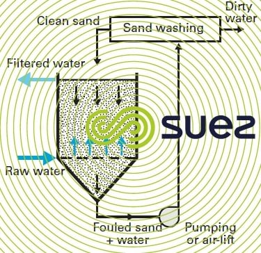
The sand bed is held in a unit that acts as a hopper. During filtration, the water flows upward through the sand bed.
The soiled sand is extracted through the bottom of the hopper and washed in a specific device positioned in the centre of the unit or outside. The "sludge laden water – sand" separation that occurs in the upper part of the bed is used to redistribute clean sand over the surface. The bed drops by (for instance) 10 to 20 cm · h–1; consequently, all the sand is cleaned within approximately 6 to 15 h.
Due to the slope of its hopper, this type of unit has a limited surface area and is, therefore, used for small outputs: small DW or process water treatment plant or IWW or UWW re-use water.
wash frequencies and wash water consumption
Wash frequency depends on a range of parameters that affect t1 and t2.
The water consumed by each wash (4 to 10 m³ per m² of filtering surface area) primarily depends on the nature and weight of the particles screened out per m³ of filter matter and on the washing method used. In particular, the combined use of washing air and unfiltered crosswash water will reduce water consumption by approximately 20 to 40% compared with water only washes.
Wash water consumption will increase:
- as the water depth over the filter matter increases;
- the greater the distance from the sludge removal troughs;
- the greater the amount of sludge to be removed;
- as sludge density and cohesion increases.
This consumption will also rise when surface washers are used.
applications
rapid downflow filtration
Depending on the case concerned, this system is used in open units (gravity flow) or closed, pressurised units (see Filters) at velocities ranging from 4 to 50 m3·h–1·m–2. This is the type of filtration that is most widely used in physical-chemical treatment systems. It is designated ‘rapid’ in contrast to older, slower filtration systems (approximately 5 m · d–1).
In potable or process water treatment, we normally have:
- direct filtration without coagulant;
- filtration with "filter coagulation" (French abbreviation: CsF) involving water that has not been clarified beforehand; the reagents used can be a coagulant, a flocculation additive and an oxidation reagent;
- filtration of coagulated and clarified or floatation treated water; in the latter case, filters are in the ideal situation which consists in receiving water that is of a virtually constant quality and that is lightly laden. Filtration rates can range from 7 to 20 m3·h–1·m–2 depending on the quality of the clarified water and on the nature of the filters used. In such cases, at temperatures of 15 to 20°C, it is quite common to obtain an output of at least 250 m³ per m² and per cycle; with a typical water consumption of 5 m3·m–2, water loss will be restricted to less than 2%.
We can also use two filtration stages in series, where each filtration stage can be preceded by coagulation with the inclusion of an additive and an oxidant.
In some recent completed projects, treatment is carried out under conditions that push this type of filtration to its limits. This is the case of the CsF in Sydney, Australia (see aquazur sand filters and clarification) where the following basic parameters apply :
- the maximum filtration velocity (24 m · h–1) is high without jeopardising the quality of the filtered water that remains excellent (< 0.1 NTU);
- the material used is homogenous, large granulometry sand (ES = 1.8 mm) forming a deep (2.1 m) sand layer. The homogenous sand filter had been selected in preference to a twin-layer filter on grounds of construction costs but also because of the amounts of wash water saved;
- ferric chloride and two polymers constitute the reagents injected (one is cationic and the other anionic) producing an extremely resistant floc that causes clogging;
- a "high energy" wash (simultaneous air and water) is used.
Tertiary filtration of wastewater can be carried out under conditions that are similar to those described above for storm water.
other types of filtration
Although the downflow current represents the most logical technical solution for filter beds with material that is heavier than water, there are also systems that have a different direction of flow:
rising flow filters
Water percolates upwards through the filter medium.. The particulate classification following expansion (washing) is more conducive to water flow and head loss is therefore lowered. However the risk of breakthrough is high and does not allow this type of filter to be used in the last stage of the process; beyond this limit, the matter expands and we have filter breakthrough.
In order to avoid this drawback, we need to allow for a system that holds the filter matter in place (e.g. a grating…) or to select a homogenous sand, continuous wash filter.
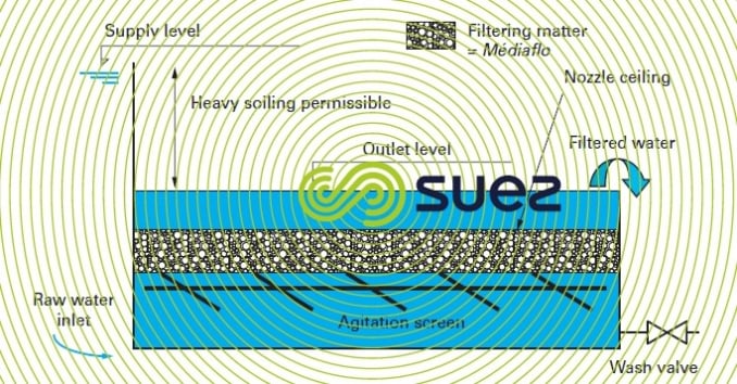
floating bed filters (figure 42)
In order to retain the benefits of a rising current, while avoiding the drawbacks of sand filters based on this principle, we can use a filter medium consisting of a floating material (lighter than water), such as expanded polystyrene (Médiaflo). This type of filter is washed without the need for a wash water tank, just by flushing the layer of water present above the filter bed (treated water losses incurred by the wash are limited to 0.8 m3·m–2).
Furthermore, all things being equal, floating bed filters provide the same results as a sand filter (see also filtrazur filters).
This system can be used in drinking water or UWW tertiary treatment processes.
twin filtration direction filters
The water to be filtered enters the filter matter from the top and from the bottom; water is recovered from within the filtering mass. In the past, a few applications used this extremely compact solution.
horizontal flow filters
This technique is sometimes used in small, very rustic water treatment plants (e.g. roughing filters using gravel).
biological filters
For drinking water, there are many applications where the effect sought is mainly based on biological phenomena:
- slow filtration of natural surface water;
- biological iron-manganese removal from ground water;
- nitrogen conversion (nitrification or denitrification) in natural water;
- mineralisation of biodegradable carbon through activated carbon filters.
Elements specific to these different types of filtration will be examined in section Biological engineering applications in potable water treatment.
EFor waste water, simple tertiary filtration already derives benefits from the biological activity of the suspended solids that are screened out; however, over recent decades, the most astounding developments have been seen in the field of Biofilters used to process carbonaceous and/or nitrogen pollution. The principles behind these biofilters, aerated and non aerated, where biological phenomena take preponderance with regard to the filtration effect, have been described in section attached growth processes and their technology in section biological filters.

Bookmark tool
Click on the bookmark tool, highlight the last read paragraph to continue your reading later
