


desalination membranes
Reading time:These membranes have been given this name because they reject ions ( salts) or organic solutes; these membranes do not have any pores. Water moves by diffusing through the actual polymer structure which is always hydrophilic and "expanded" by the water.
As we shall see further on, these membranes are themselves classified as reverse osmosis and nanofiltration membranes.
crossing through the membrane
The ideal RO membrane will only let water through, rejecting all solutes with the exception of a few organic molecules that are very similar to water (low gramme-molecular weight and strong polarity, e.g. ethanol, methanol and formaldehyde).
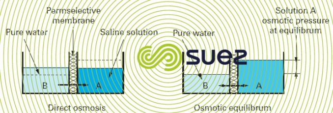
Mechanism: if we separate a concentrated saline solution from a dilute solution using this type of membrane (also designated as permselective) (figure 51), the chemical potential differential tends to make the water move from the low potential compartment to the higher potential compartment to dilute the latest (direct osmosis). When the mechanism is in equilibrium, the pressure differential thus created is termed the system’s osmotic pressure (figure 51). If we seek to prevent this diffusion from occurring, we need to apply pressure to the "salty" fluid and this pressure must be the same as the osmotic pressure; if we want to "reverse" the direction of flow, the pressure must be higher than the osmotic pressure.

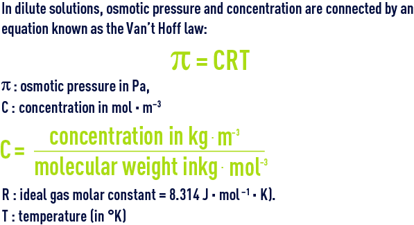
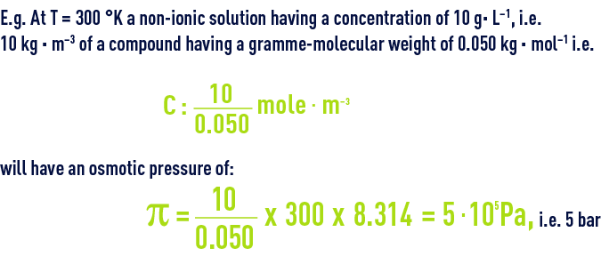
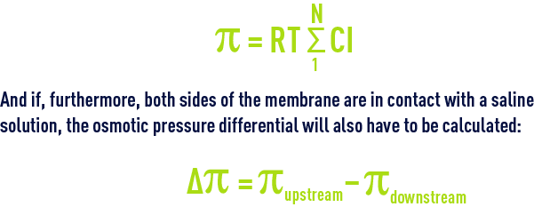
In dilute solutions, osmotic pressure and concentration of the solute are connected by an equation known as the Van’t Hoff law :


Given the same concentration :
- for a compound that has gramme-molecular weight of 0.5 kg · mol–1, π = 0.5 bar;
- for a macromolecule that has gramme-molecular weight of 50 kg · mol–1, π = 0.05 bar …
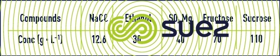
We can see that the smaller the molecule (low gramme-molecular weight ), the higher the osmotic pressure created by the same concentration. Table 16 provides the concentrations of various compounds that apply a same osmotic pressure of 10 bar.
We shall see that, in the case of ionised salts, the same formula will apply by using the molar concentration of each of the ions and this, in the case of a salt made up of totally dissociated monovalent ions, will double the osmotic pressure applied compared with the non-dissociated compound having the same gramme-molecular weight.
When several ions and non-ionic compounds contribute to the osmotic pressure:
In 35 mg · L–1 seawater, π = 28.5 bar or approximately 0.8 bar/g of dissolved salts.
Figure 52 shows that the Van’t Hoff law is only obeyed by «low concentrations», e.g. up to 30 g · L–1 for NaCℓ.
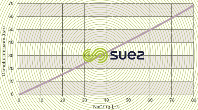
In fact, in order to produce “pure” water from a saline solution, we need to exceed the solution’s osmotic pressure; in the case of brackish water containing a few grams of salt per litre, we will need to exceed 5 to 15 bar of pressure and, in the case of seawater (35 to 45 g · L–1), pressures of 50 to 80 bar.
A second phenomenon will enhance this effect. As shown in figure 53, when water is transferred, the molecules and ions screened out by the membrane tend to accumulate along the membrane, in the border bed and thus increase the salinity actually "processed" by the membrane and, therefore, the osmotic pressure that has to be "overcome" in order to desalinate the solution. This situation generates higher energy costs but also the risk of precipitation entrainment when the solubility product of one of the cation-anion couples present is exceeded in the border bed along the membrane.
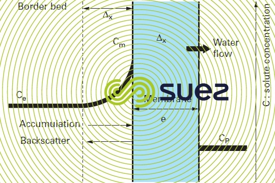
This phenomenon is termed concentration of polarisation of the membrane concentration and is characterised by the following coefficient:
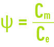
where:
Cm: concentration of the liquid in contact with the membrane.
Ce: concentration of the liquid to be treated.
This phenomenon can be minimised by increased crossflow of the membrane’s upstream side, limiting the border bed thickness and facilitating back- scattering of the rejeted solutes; however, this means limiting the desalinated water fraction. In industrial desalination systems, the aim is to achieve a coefficient y between 1.05 and 1.4.
For the purpose of describing the phenomena observed, the most widely used model uses diffusion laws and, as first estimate, water flux are proportional to the effective pressure differential (ΔP – Δp) and salt flux to the concentration differential (ΔC).
for water
We can write :

where :
Qp water flow across the membranes,
Kp: membrane’s water permeability coefficient,
S: membrane surface area,
ΔP: pressure difference on both sides of the membrane,
Δp: osmotic pressure difference on both sides of the membrane,
Kt: temperature coefficient.
The water flow across the membrane is, therefore, directly proportional to the effective pressure gradient.
Coefficient Kt allows for water viscosity. This viscosity declines as the temperature rises. Output will, therefore, be higher as the temperature rises (2.5 to 3% difference per degree in the vicinity of 15°C).
for salts
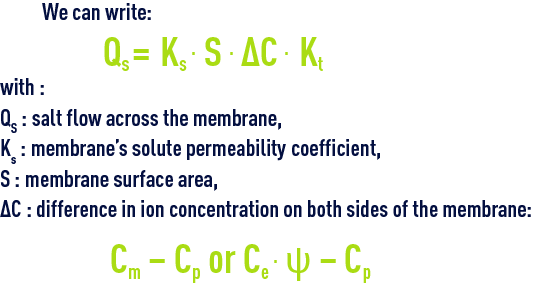
Kt: temperature coefficient.
The salt flow is directly proportional to the gradient of the concentration across the membrane and, for a given membrane and solution, its value will be independent of the pressure applied.
Salts concentration in the produced water (permeate) will be provided by the ratio between the two preceding equations.
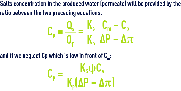
This concentration (quality of water produced) is proportional to the concentration gradient across the membrane and inversely proportional to the effective pressure gradient (ΔP – Δp).
With anyRO systems, therefore, we note the following trends (table 17) arising from equations (1) and (2).
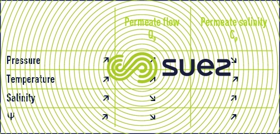
In practice, we frequently observe that the rise in pressure does not increase quality and flow as much as anticipated by equations 1 and 3 above; in effect:
- when the flow rises, Y increases and, therefore, Δp and ΔC increase; therefore, any flow and quality gains will be reduced;
- furthermore, while solutes are subject to backscatter, macromolecules and colloids accumulate on the membrane (see fouling); consequently, before increasing the flow, we need to check that the physical quality of the liquid to be processed will allow this to take place; should this not be the case, the effect could even be reversed; fouling and polarisation concentration will become preponderant. These problems are also examined in chapter Separation by membranes.
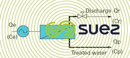
utilisation and membrane water balance
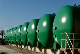
The simplest osmosis system, figure 54, will comprise the following elements :
- a high pressure pump to provide the system with energy;
- a module or serie of modules;
- a valve fitted on the discharge side for the purpose of maintaining the pressure within the system.
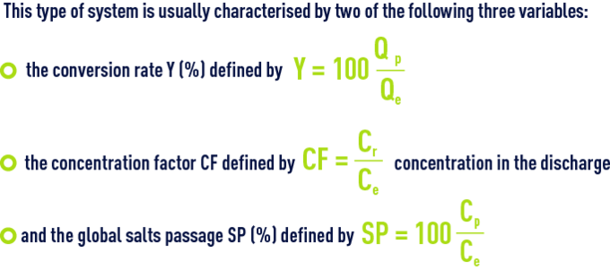
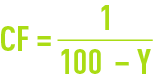
In fact, one of these, the SP, is very dependent on the choice of membrane.
The others, Y and, therefore CF, depends on the decision to use more or less raw water for a given output; however, this is a fundamental choice:
- As Y rises, the cost of energy per m³ produced, E, decreases because less water has been pressurised in order to achieve the same output;
- However, at the same time, Cr and CF increase and, consequently, the quality of the water delivered declines because, on one hand the average concentration in front of the membrane increases from Ce at the intake to Cr out the outlet (which means that, in the preceding equations, Ce needs to be replaced by average concentration along the length of the membrane) and, therefore, the amount of salt increases; also, the flow of water decreases because Qp decreases (indeed, the osmotic pressure p which is proportional to
 rises).

Notes:
- In chapter Separation by membranes, we shall see the positive consequences (less discharge to be disposed of) and also the frequently negative consequences (scaling, fouling) generated by increased Y and, therefore, by increased CF.
- The specific energy does not decline at a uniform rate as Y increases; a minimum is reached before an increase is observed as the useful pressure ΔP – Δp becomes too weak.
reverse osmosis
These membranes discharge ionised salts and, less easily, non-ionic molecules and very little, if any, dissolved gases: O2, CO2…).
In chapter Separation by membranes, we shall see that this term covers membranes having a SP of:
- 0.3 to 5 % for monovalent ions;
- 0.05 to 1 % for bivalent ions.
These figures are seen to be quite low. Therefore, as an initial approximation, we often have to neglect CP in favour of Ce or Cr, thus simplifying the equations referred to above and allowing to write :
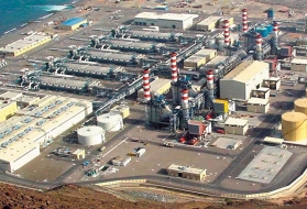
These membranes are used in all desalination systems:
- seawater desalination to obtain potable or process (boilers…) water;
- brackish water desalination (same applications);
- freshwater desalination to obtain demineralised or even ultra pure water;
- …
However, as osmotic pressure is very variable, different membranes and modules will be used; the differences will mainly arise from their utilisation pressures (5 to 80 bar) and their filtration flux (10 to 40 L · m–2·h–1); this, in turn, leads to widely varying investment and operating costs (see chapter Separation by membranes).
It should also be noted that these membranes fully screen out all macromolecules (PM > 300 D) and, a fortiori, all particles including the finest colloids.
nanofiltration
This RO membrane variant has been introduced more recently and is characterised by:
- relatively high passage of monovalent salts 10 to 80 %;
- much lower passage of bivalent salts 1 to 10 %;
- an organic solute passage that is equivalent to that of osmosis membranes.
Therefore, the main benefit of these membranes lies in the fact that they tolerate a high passage of monovalent salts (which make the greatest contribution to osmotic pressure), limiting ∆π and, therefore, the energy that needs to be used in order to achieve:
- partial desalination combined with an acceptable level of water softening;
- water purified of its organic pollution, for instance, very good colour removal from natural water, removal of THM precursors and even of most pesticides…
Bookmark tool
Click on the bookmark tool, highlight the last read paragraph to continue your reading later
