


filtration throught a mechanical support
Reading time:screening and Micro-screening
In fact, this is a relatively coarse filtration carried out through a thin sheet made of a metal or plastic fabric or of filtering elements that have regularly placed openings. Depending on the size of the openings, we will have micro-screening or macro-screening (table 12 and barscreening, straining, comminution).
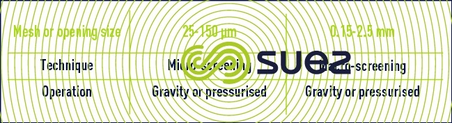

“Removal capacity” is defined by the mesh opening: it is assumed that the system will eliminate all particles that are larger than the size of the mesh opening. In fact:
- as the system operates, the screened out particles will partially block the mesh and the filter will then screen out particles that are below the removal capacity size;
- the filter will only remove particles that are larger than its pores when these particles cannot be deformed. Under pressure and accompanied by high head loss, much larger deformable particles may pass through the filter (e.g. bacterial floc).
In gravity operation mode, these filters are usually designed for a low maximum head loss of some tens of centimetres of head in consideration of the fragile nature of the fabrics used; these fabrics could tear under the impact of pressures that rise too high during operation and/or washing.
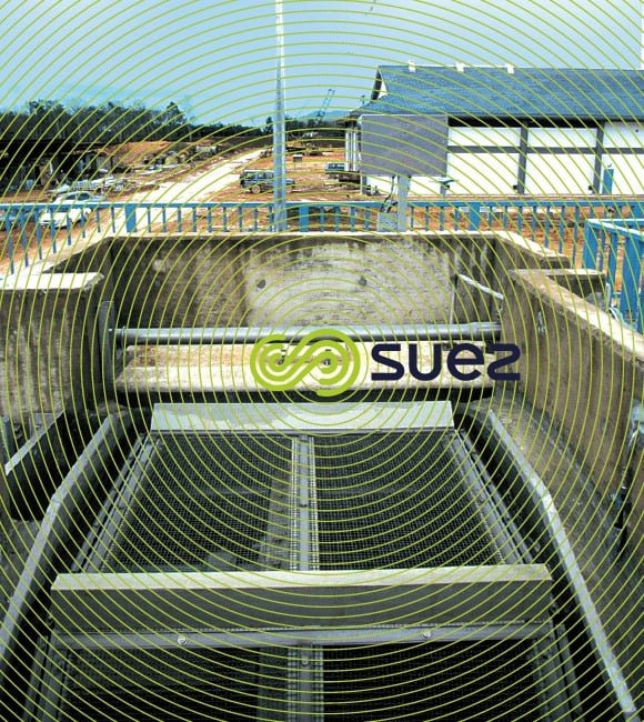
free surface straining
These units using drums or belts that are partly submerged in water, can rotate continuously or intermittently, exposing their fabric so that it can be washed using a pressurised water jet.
micro-straining
The main purpose of a micro-strainer consists in removing plankton from surface water; the micro-strainer will simultaneously remove large suspended solids and plant or animal debris found in the water. A micro-strainer can also be used after biological purification or lagooning for removing residual suspended solids.
Micro-straining is not recommended upstream from a clarification line unless the water contains more than 100,000 micro-algae cells per mL; in effect, micro-straining will reduce the plankton content by between 40 and 70%. For comparison purposes, a good clarifier (or flotation unit) will achieve a 75 to 90% reduction without any pre-oxidation, and 85 to 99% reduction with pre-oxidation. The use of micro-strainers should be restricted to water that only has a low suspended solids content. Micro-strainers will not have any effect on colour or on dissolved organic matter and will only remove the coarsest fraction of suspended particles.
macro-staining
This system is used to protect pumps or certain types of clarifiers against detritus (plant debris, plastic bags …).
pressurised straining
Water straining (micro or macro) can be carried out under pressure. In such cases, the purpose of this method consists in :
- either providing protection against relatively large (a few mm) blocked openings; washing sprayers, some once-through or open recirculating cooling circuits, with a 0.5 to 5 mm straining threshold. Upstream from hollow fibre UF membranes, a finer mesh (100-200 μm) will be required;
- or for continuous removal of fine matter (micro-straining). The filter’s removal capacity can be lowered to 50-75 μm or less and the unit incorporated into a treatment line. This can apply to the injection of seawater in secondary oil recovery applications.
These are designated automatic regeneration rotary filters (based on the technique used and on filter washing) or, occasionally, pressurised mechanical filters. They can be used at 0.5 to 2 bar differential pressures.
filtration through cartridges and candles
object
In water treatment applications, these filters are used to resolve one of the following problems:
- extremely high filtrate quality, obtained from very lightly laden water such as:
- condensate from HP boilers, in start-up or continuous operation mode;
- supplying ultra pure water circuits;
- protecting reverse osmosis membranes;
in ultra pure water applications, we can aim to eliminate increasingly fine particles down to 0.2 μm (bacteria) and, despite the cost, consumable supports may be used;
- protection for hydraulic circuits such as:
- seawater injected for secondary recovery purposes;
- cooling or machining circuits;
for preventing granular particle entrainment, especially for preventing any loss of filtering matter (fibres, resins, activated carbon...) or the injection of particles brought in from the atmosphere. The filtration level can vary from 200 to 1 μm.
selecting media
TThis selection will be based on desired efficiency and operational parameters.
filter efficiency criteria
TThe constructor will indicate nominal retention thresholds for a particular support filtration mechanism and suspension to be processed. These thresholds refer to the finest particles screened out, without specifying a strict removal percentage.
The "absolute" retention threshold is the diameter of the smallest particle for which the index has achieved the target value for a particular application.
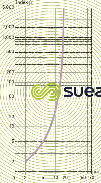
This index β = (number of particles in the water to be filtered/number of particles in the filtrate) is measured by filtering a control suspension.
An electronic laser counter is used to carry out the count. Figure 37 (β based on the particle diameter) provides an example of the result obtained on a test filter. According to the industry, the target index b can be "5 000/1" or "2 000/1" or "200/1".
It should be noted that going from a nominal retention threshold to an absolute retention threshold can represent a cost which can be up to many of tens times higher.
Fouling index (FI/SDI) (see section measuring global parameters : when this index falls, it represents a drop in a water's clarification or desalination membrane fouling capacity (see section Membrane separation); it is often (colloidal water) far more significant than just the number of particles that are larger than the given threshold(s).
operation parameters
- regeneration or consumption of the support matter;
- head loss and permissible cycle duration;
- suspended solids concentration in the water to be treated;
- after any regeneration cycle, there is a danger that the support matter or matter held back within the support medium will salt out.
These parameters must be taken into consideration when selecting the equipment and filtration support mechanism.
filter types
We can distinguish:
- consumable cartridges, equipped with:
- pleated membranes made from paper, polycarbonate films or Nylon 66, non-woven, heat welded textiles (polypropylene);
- felts, non woven, spooled textiles, plastic agglomerates.
These filters can have absolute retention thresholds (see above) ranging from 0.1 to 20 μm;
- cartridges that can be backwashed with water, equipped with :
- fibres and sintered metals, with nominal thresholds ranging from 6 to 100 μm;
- monofibre bristle fabric (polyester) having nominal thresholds of 200 to 100 μm.
The backwash option only applies to high nominal threshold cartridges used on lightly laden water;
- regenerating candles equipped with:
- sintered metals or ceramics ;
- plastic agglomerates.
Regeneration is less frequently carried out by backwashing with filtered water than by other specific methods that are compatible with the supports (vapor, acids, ultrasonics…).
In general, whether we are dealing with backwashed cartridges or regenerating candles, fouling water filtration will gradually deteriorate these support mechanisms and they will foul throughout the thickness of the filter itself; consequently, they have to be replaced after a certain number of cycles.
pre-coat filtration
The desired final filtration will have a removal capacity of approximately one mm and the filtering layer will consist of:
- either the filtration cake itself when particle size and concentration (0.5 to a few g · L–1) are appropriate, e.g.
- carbonated "cloudy liquor" from sugar processing plants;
- "tank floor" brewing lees;
- hydrometallurgy pulp;
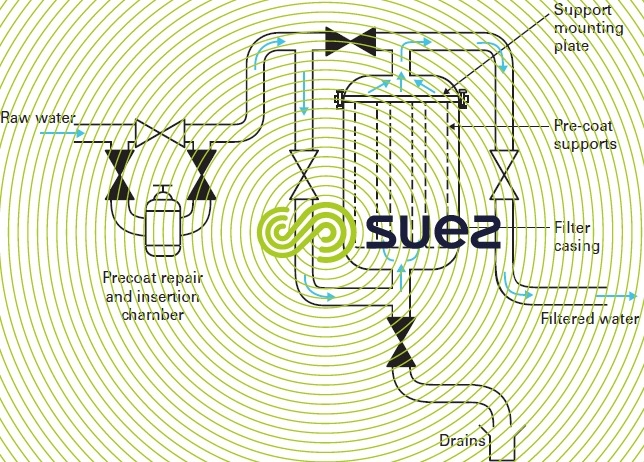
- or a pre-coat consisting of a filtration “aid” used at the start of the cycle (cellulose, diatoms, micro-resins) which, afterwards, is used as an active filtration layer as, for instance, in the case of micro-resins that are used to filter and demineralise power station condensates. Figure 38 provides a schematic diagram of a pre-coat filter. Once the maximum head loss has been reached, this pre-coat is broken down by scraping or by injecting air and backwash before a new cycle is started.
In fact, the maintenance costs associated with this type of system and, above all, the cost of pre-coat materials (lost at the end of each cycle) are such that, with the exception of self-forming pre-coats, these systems have been dropped in favour of the systems described earlier and which, in most cases, involve clarification membranes (see section Membrane separation and chapter Separation by membranes).
Bookmark tool
Click on the bookmark tool, highlight the last read paragraph to continue your reading later
