


dialysis membranes
Reading time:In dialysis, the solutes migrate through the membrane that is impermeable to water. The various processes can be differentiated through the driving force used (pressure, concentration or electricity potential differential) and through the type of membrane used.
piezodialysis (pressure gradient and amphoterous membranes)
No industrial application.
simple dialysis (concentration gradient)
The impurities migrate in order equalise the chemical potential (low gramme-molecular weight organic solutes and salts) on both sides of the membrane; if the phase is renewed sufficiently while concentration is taking place, almost 100% of the impurities will be removed.
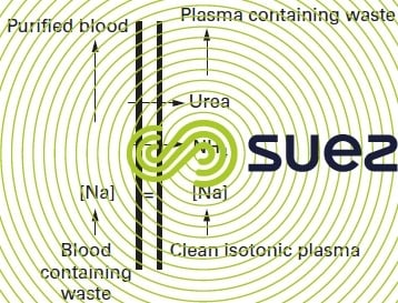
The main application for this system is haemodialysis (figure 65 – artificial kidney) used to purify blood (removing salts, urea etc.) in patients suffering from renal deficiency, by bringing the blood into contact via a mesoporous membrane with the dialysis solution containing mineral salts. The membrane allows low molecular weight nitrogen compounds and salts through (urea, uric acid etc.) while totally screening out proteins. The unwanted elements, therefore, are the only ones to be eliminated and the isotonic balance can be re-established by adjusting the salt content of the dialysis solution.

électrodialyse (electrical field gradient)
principle
When an ion-rich liquid is subjected to an electrical field via two electrodes between which a continuous potential differential is applied, the cations will move towards the negative electrode (or cathode) while the anions will move towards the positive electrode (or anode). If nothing prevents this movement, the ions will discharge onto electrodes of the opposite sign and we have electrolysis.
However, if we position a series of selective dialysis membranes between these electrodes:
- some, being cationic, will only be permeable to cations;
- others, being anionic, will only be permeable to anions. If these membranes are positioned as shown in figure 66, we limit ions migration because anions cannot pass through negative membranes, or cations through positive membranes.
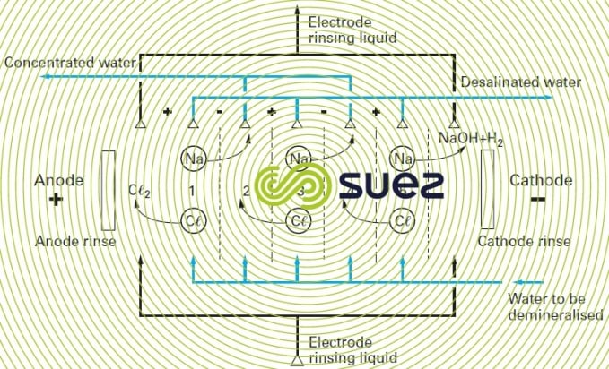
Thus, in the case of the cell comprising three pairs of membranes, where compartments 1, 2, 3, 4 and 5 are supplied with a sodium chloride solution, the ions in compartments 1, 3 and 5 will move to compartments 2 and 4 under the effect of the electrical field generated by the electrodes.
Under these conditions, the water in compartments 1, 3 and 5 become salt-depleted ("demineralising"), while the water in compartments 2 and 4 becomes concentrated.
For each Coulomb injected into the system, we see a valence-gram of anions and cations leaving each demineralisation compartment (1,3 and 3) and this valence-gram is added to the valence-grams already present in the concentration compartments (2,4).
As the potential differential is proportional to the number of cells, the energy required for each kilogram of salt removed remains more or less constant (0.6 to 0.8 kWh per kg of salt eliminated),
Thus, this process allows the water to be demineralised. On the other hand, non-ionised molecules and colloids remain in the treated water; this is the case of silica, regardless of its form and also the case of most dissolved organic products and of all micro-organisms.
The process also suffers from the following drawbacks:
- it will not produce highly demineralised water: in effect, the electrical resistance of the relevant compartments would be too high, generating ohmic losses. In general, it is not reasonable to try to reduce the salinity of the water produced to less than 200 mg · L–1 ,
- water costs rises steeply as incoming salinity increases; in effect:
- on one hand, as already discussed, power consumption is proportional to the amount of salts removed;
- on the other, if we want to avoid selectivity losses caused by ion back scattering under the effect of an excessively high concentration gradient between the two sides of the membrane, we need to limit this gradient. Furthermore, in fact, the electrolysis market is limited to water with a salinity of less than 2 g · L–1.
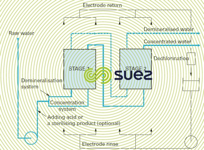
- salt elimination rate limitations: depending on the internal hydraulics of the electrodialysis apparatus (turbulence along the membranes), the best result will be a 70 to 85% salt removal efficiency per pass (between 15% and 30% of salts crossing the membrane); therefore, a configuration involving recycling or several passes (figure 67) may be required.
- the need for pre-treatments:
- removal of turbidity (to avoid deposits, especially in poorly irrigated areas),
- rmetal content reduction, e.g. Fe and Aℓ < 0.3 mg · L–1, Mn < 0.1 mg · L–1.
- reduction of salts likely to precipitate in the concentration compartments, bearing in mind that, in the case of electrodialysis, polarisation tends not only to superconcentrate ions in the water to be treated but also to alter pH (local superconcentration of OH– or H+ ions, which can reinforce the tendency to precipitate of some compounds). Membranes, having the same chemical nature as the ion exchanger resins, also share the latters' limitations (see section main types of ion exchangers): in particular, sensitivity to oxidants (Cℓ2 < 0.1 mg · L–1), and above all, anionic membranes will be irreversibly poisoned when the water to be treated contains organic molecules likely to be adsorbed over these membranes.
polarity reversal electrodialysis ("PRE")
In order to avoid any danger of scaling, one elegant solution consists in regularly reversing electrode polarity (e.g. 5 minutes every 30 to 60 minutes) thus momentarily switching concentration compartments and desalination compartments and, therefore, the position of the polarisation layers that will move to the other side of the membrane.
Water "produced" during these inversion phases must be discharged.
This technique is used on all modern electrodialysis units because it allows pretreatment to be simplified but at the cost of a noticeably more complicated installation:
- automatic valves allowing water to be discharged into the drains during the inversion phases;
- electrodes that are all required to withstand anodic corrosion.
The main field using electrodialysis is organic (and even colloidal) solution desalination, e.g. whey desalination. In this field, its only competition comes from ion exchangers. In effect, used in this type of case, reverse osmosis would create a concomitant concentration of all species present and produce demineralised water and a whey concentrate, whereas electrodialysis only removes ionised species. In water treatment applications, this system is used on low salinity brackish water (0.8 to 2 g · L–1) when the aim consists in just removing a proportion of the salts (drinking water); in this case, this method is in direct competition with low pressure reverse osmosis and even with nanofiltration (see chapter Separation by membranes).
It should also be noted that all industrial installations use flat membranes fitted in systems that are similar to filter presses.
water electro-deionisation
In the preceding paragraph, we discussed electrodialysis and explained why it cannot be used for cost-effective demineralization of water with less than 150 or even 200 mg·L–1 of total salinity (see rising electrical resistance in dilution compartments). In order to avoid this difficulty, some 50 years ago, thought was given to filling these compartments with a bed combining a comprehensively regenerated strong anionic and cationic resin (H and OH– form), figure 68.
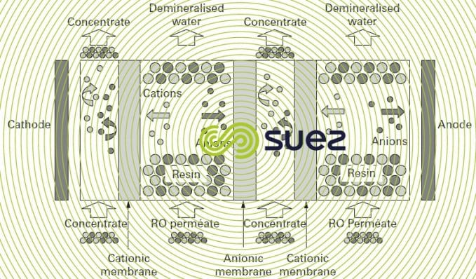
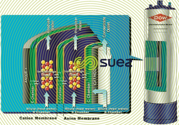
In such cases, demineralisation and electrodialysis mechanisms are the same with the notable exception of the electrical conductivity of the compartments; this conductivity is no longer due to the ions present but to the resin that is “compacted” between 2 selective membranes. The ions migrate to the electrodes by travelling from one grain of resin to the next until they reach the selective membrane that transfers the ions into one of the concentration compartments. (Note: this transfer can be likened to a series of attachments followed by the electrical regeneration of the resins).
This method allows the water to be completely de-ionised and occurs at the same level as for a combined bed (see chapter Using ion exchangers) mais sans employer de réactifs chimiques.
In fact, it wasn't until the 1990’s that we saw the emergence of the modern de-ionisers that use compartments that are a mere few millimetres thick. Under these conditions, the electrical resistance of separation membranes can no longer be ignored.
The basic unit comprises a stack of compartments with their manifolds for water to be demineralised, their concentrate recovery systems and their electrode sweeping (depending on the constructor, these units can be used to process between 1 and 15 m3·h–1). Then, these units can easily be assembled in parallel.
The system is subject to the following limitations :
- given the narrowness of the channels and the need to leave the resin mixture bed completely clean (there is no option allowing the bed to be "cleaned of any fouling"), the water used must have perfect physical properties (no colloids);
- in order to limit reactions at the electrodes, the water must have undergone partial demineralisation to a minimum of 40 μS ·c m–1.
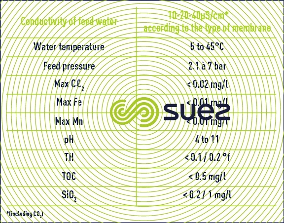
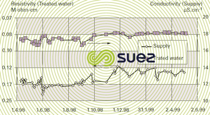
The combination of these two limitations limits the use of EDI as a polishing stage after a reverse osmosis demineralization stage or even after a double osmosis stage (series-permeate). In this case, figure 69 illustrates the typical results achieved after one year of operating an EDI system and table 19 regroups the qualities of water obtained and the unit's operating conditions. (Attention: the scales are dissimilar).
Reminder: 10 μs · cm–1 is equivalent to 0.1 MΩ·cm.
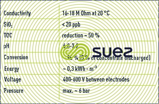
0,.1 to 0.,3kWh.m3 of energy consumption
It should be noted that:
- Silica and boron ions are the least well screened out together with dissolved gases and especially CO2;
- An extremely valuable bactericidal effect for ultra pure water is created by the extreme pH values (2 or 11) in the border beds along the resin grains and the membranes.
The most conventional EDI applications are those requiring low quantities (< 50, even 100 m3·h–1) of ultra pure water typical of process water used in the following industries:
- electronics;
- pharmaceuticals;
- energy.
The chapter Industrial processes and effluent treatment explains how electro-deionisation is used in these first two cases. In the latter, the main benefit is that there is no need reagent for the regeneration and this is particularly advantageous in systems seeking to minimise discharges, and even to achieve zero discharges.
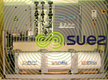
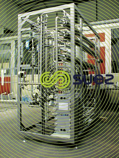
Photo 8 shows, in an assembly bay, a Centripur system intended for a pharmaceutical laboratory, output ~ 2.5 m³/h; the same skid houses the two membrane stages (see four pressure tubes) and one electro-deionisation stage ("filter press" type stack at the base of the skid).
Bookmark tool
Click on the bookmark tool, highlight the last read paragraph to continue your reading later
