


sludge contact clarification
Reading time:This type of clarification simultaneously applies the principles of solids contact flocculation (see flocculation with sludge contact) in combination with the hindered settling of flocculated particles (see different types of sedimentation). The water to be treated, having previously been coagulated, is put into contact with the pre-existing sludge: there is a far greater possibility that the colloids in the water will collide with the floc from the sludge blanket and this results in a spectacular increase in flocculation and sedimentation rates, hence the designation of accelerated clarifier often used for the equipment involved.
These are flocculation-settling tanks because the flocculation zone is an integral and optimised part of the equipment.
It is important that we emphasise the fact that these clarifiers have a sludge concentration zone that is isolated (below or on the side) from the actual sedimentation zone: thus, the latter is only affected by the rectilinear (BC) component of the Kynch curve (see flocculation with sludge contact) the remainder of the Kynch curve will then apply respectively to the sludge concentrators included in the settling tanks (CD) and to any thickening units (DE).
As already stated in the section flocculation with sludge contact, these principles can be applied in two configurations.
sludge recirculation clarifier
Sludge that has been clarified and, if applicable, skimmed, is re-injected into the water to be treated in order to produce as thorough a mixture as possible.
This recycling can be:
- either external: sludge is recovered as it thickens using a pumping system that has been designed in such a way that it does not destroy the floc (e.g. the Densadeg, see Flocculators – settling tanks – flotation units) and the recycled sludge is re-injected into the flocculation reactor;
- or, more frequently, internal (figure 26); the same arrangement (screw, turbine, injector…) used to return sludge into the flocculation zone is also used to provide the turbulence required for flocculation to take place (please refer to chapter Flocculators – settling tanks – flotation units for examples: Accelator, Circulator, Turbocirculator).
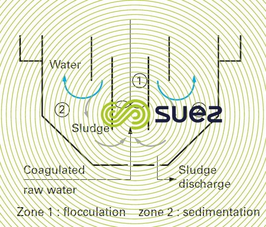

sludge blanket clarifier
In units operating according to this principle, flocculation and clarification are fully integrated: the sludge blanket being the main flocculation and settling zone.
Water, having been coagulated, percolates vertically upwards through the flocculated matter during clarification (zone 2 in figure 27).
Some units of this type comprise juxtaposed inverted pyramidal cells into the base of which a hose injects the water to be clarified; these systems have hydraulics that do not allow them to operate at an upflow speed (calculated over the total ground area) much different to that of static settling tanks.
Conversely, if coagulated water is evenly distributed over the entire floor area of a flat bottomed tank, the vertical streams will be quite vertical and generated by upward velocities that are identical at every point in the sludge blanket.
This blanket then has a certain cohesion that renders it capable of accepting rising velocities that are higher than those applicable to an isolated floc. This cohesion explains the "elasticity" of the sludge blanket which, just like a spring, tends to compress under the effect of gravity (particle sedimentation) but will expand to a greater or lesser extent under the effect of the water’s upflow. If the rising velocity is too high, the sludge blanket’s sedimentation rate will no longer be sufficient and the diffuse floc is drawn away with the water.
Sludge blanket cohesion can be measured by calculating its sludge cohesion coefficient K (see section Consumption and production waters examination for the measurement method). This is, therefore, an essential sludge blanket clarifier design parameter.
Pulsation used in the Pulsator units and their lamellar derivatives (see chapter Flocculators – settling tanks – flotation units) is a mechanism used to inject high energy that causes the blanket to homogenise and generates optimum flocculation, followed by a "rest" period (lower velocity) that allows to compress again. In this case, it should be noted that the mean velocity remains higher than the velocity that could be maintained under permanent conditions.
combination with lamellar settling
In a sludge blanket clarifier (recirculation or sludge blanket), using lamellar modules in the upper, clear water zone enable us to:
- improve clarified water quality, for the same rising velocity, by holding back the residual floc that tries to break away from the sludge blanket;
- increase the throughput processed per unit, for the same quality of water (e.g. Pulsatube, Densadeg, see chapter Flocculators – settling tanks – flotation units).
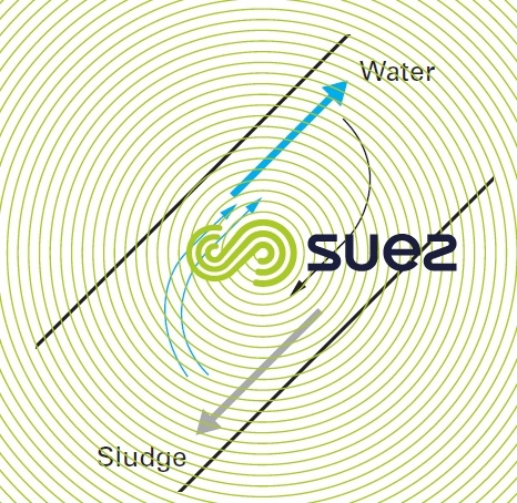
Similarly, if we insert sloping plates into a sludge blanket that is kept in a suspension, we will notice that the sedimentation rate will rise within the sludge blanket: sludge will be deposited on the upper surfaces of the plates and will slide downwards without experiencing any braking effect from the water's rising flow. Rather, the water will tend to flow along the lower surfaces of the plates (fig. 28); true density currents will thus be created, enabling the solid-liquid separation to take place faster.
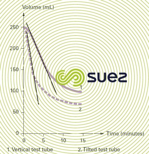
This phenomenon can easily be observed in the laboratory, by comparing the Kynch curves (see section different types of sedimentation) obtained for the same sludge in both a vertical test tube and one that is titled by approximately 60° to the horizontal (figure 29). This type of "sludge blanket" / lamellar clarification combination enables us to concentrate the sludge blanket and to reach velocities that are 2 to 3 times higher than in the traditional accelerated sludge blanket clarifiers. This is the principle that underlies Superpulsator and Ultrapulsator clarifiers (see technology chapter Flocculators – settling tanks – flotation units).

Bookmark tool
Click on the bookmark tool, highlight the last read paragraph to continue your reading later
