


Fluidisation
This technique is applied in various water treatment units:
- fluidised bed carbonate removal: Softazur;
- fluidised bed biological reactors, e.g. Anaflux;
- fluidised bed dryers and furnaces (e.g. Thermylis: fluidised bed furnace);
or during one single phase of the process (washing or grading materials):
- granular bed biological reactors and filters that are water-washed only;
- ion exchangers with combined beds and multi-medium filters (grading and separating materials).
In a reactor containing a few solid particles crossed by a fluid travelling upwards, each of the particles will be subjected on the one hand to the force of gravity and, on the other, to friction caused by the passage of the fluid. The result is a balance that establishes a critical velocity (see Stokes law if the flow is laminar). When the rising velocity is lower than the critical velocity, the particle will settle; however, if the rising velocity is higher than the critical velocity, the particle will be drawn upwards by the liquid.
Fluidised beds do not behave like a series of free particles; on the contrary, the fluidised bed being formed of a dense system of particles that interact with each other, it behaves more like a fluid, hence the term "fluidisation".
In practice, when a granular mass having a uniformity coefficient of 1 is placed in a column and subjected to increasingly high velocities, we obtain the results summarised in graphs a and b given in figure 45.
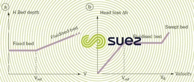

Initially, the material is not expanded (fixed or "compact" bed) but expansion increases with the velocity of the liquid and the "fluidised bed expands".
Conversely, the head loss (curve b in figure 45) starts by rising in the compacted bed but then remains constant between two characteristic velocities:
- Vmf: minimum fluidisation velocity;
- VE: bed entrainment velocity.
It should be noted that this is made possible, despite growing friction levels, because, as it expands, the bed’s e rises (see section fundamental equations).
Both these critical velocities themselves depend on the size and density of the particles and also on the fluid’s viscosity and, therefore, on its temperature. It should be noted that, beyond velocity VE, the bed looses its cohesion and its matter is gradually drawn away in the rising current.
If, as is usually the case, the granular mass’s uniformity coefficient is greater than 1, nevertheless, the same bed’s consistent behaviour should be noted and velocities Vmf and VE will remain clearly defined on the head loss graph; however, the same fixed bed – fluidised bed – entrained bed transitions are far less clear-cut if we only monitor the bed depth.
In fact, most of the time, fluidized beds are operated at velocities that produce a 20 to 40% expansion rate compared with fixed beds.
In general, the satisfactory operation of a fluidised bed reactor will be conditional on:
- good fluid distribution in the bottom of the reactor;
- homogenous and abrasion-resistant contact matter.
It should be noted that, providing that the volume of gas in the bed is not too high (< 10%), triphasic systems (solid – liquid – gas) will behave in the same way as diphasic beds and that fluidisation homogeneity will be conditional on a good distribution of the liquid.
IIn biological treatment applications, by ensuring that the bed of particles is thoroughly combined with the fluid to be treated, we can maximise exchanges between the biomass that is colonising this matter on the one hand and this fluid on the other. At the same time, in order to maximise the available colonisation surface area, it is advisable to use low effective size materials (0.2 to 0.5 mm). Consequently, fluidised beds are often quoted as being the most efficient reactors(e.g. in terms of kg of BOD removed/m³.d) but not necessarily the easiest to run.
In particular, we need to be aware of the fact that as the biomass grows, the grains will become coated with a low-density film; this film will reduce their fluidisation rate and increase bed expansion. Therefore, we need to have means (pumps, injectors …) used to coat these grains while keeping a seeding level that is appropriate for maintaining reactor performance. The materials that can be used are sand, biolite…
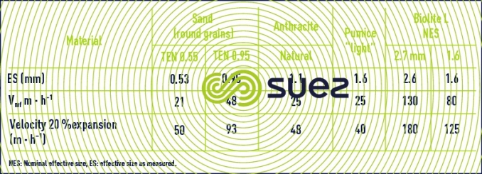
Table 14 provides a few figures for fluidisation velocities measured on actual samples.
Bookmark tool
Click on the bookmark tool, highlight the last read paragraph to continue your reading later
