


designing settling tanks
Reading time:Two criteria are used for the purpose of calculating the surface area of a settling tank :
- the hydraulic surface loading that is characteristic of the volume of water that can be processed by the unit of surface area and unit of time (m3·m–2.h–1);
- the solids loading that is characteristic of suspended solids that will settle per unit of surface area and per unit of time (kg · m–2.h–1).
The most limiting of the two calculations will constitute the structures dimensioning parameter.
influence of the hydraulic surface loading
This loading is directly linked to “free or flocculated” suspended solids sedimentation rate and the preceding paragraph"different types of sedimentation" shows how this rate can be determined and how to calculate the ensuing minimum surface area.
influence of solids loading
In flocculated particle hindered settling which includes thickening phenomena, mass flow rate is usually a determining factor when calculating settling tank surface area.
Let us consider a settling tank having a section S, fed with an incoming flow QE with a suspended solids concentration CE; sludge is drawn off from the bottom of the settling tank at a flow rate of QS with a concentration CS.
In the absence of chemical or biological reactions affecting suspended solids concentration, and if we consider a 100% elimination efficiency, we will have:
- treated flow Q = QE – QS
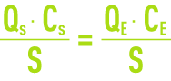
- materials balance ·CS = QE·CE
or as solids loading:


The solids loading that will settle is provided by the Kynch curve. For a given point on the Kynch curve, having a concentration Ci, the sedimentation rate Vi is provided by the tangent at this point. The corresponding mass flow is Fi = Ci·Vi.
To this mass flow Fi, we need to add the draw off mass flow FS provided by CiVs = Qs/S.
The total solids loading will be F = Ci·Vi + Ci·Vs.
Figure 18 illustrates the changes undergone by these different flows. Flow F has a minimum FL which is associated with a critical concentration CL, which requires the settling tank to have a minimum section of Sm such that:
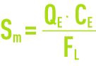
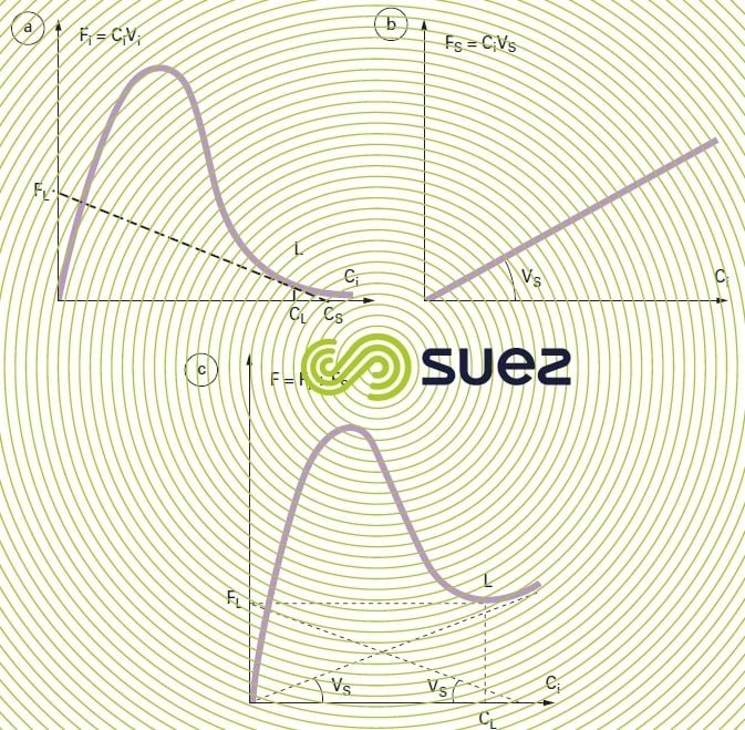

This specific point L can be determined direct on the solids loading curve F (figure 18 c) using:
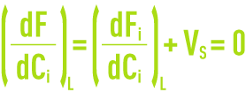
Point L is, therefore, the point on flow curve Fi where the slope of the tangent is equal in absolute value to the draw-off speed Vs (figure 18 a). These results can be expressed in a variety of ways by considering the Kynch curve. Limit flow FL at point L is provided by:
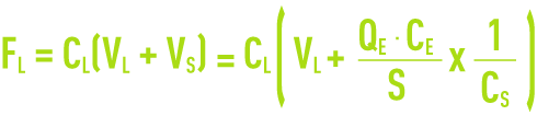
VL being the sedimentation rate at point L.
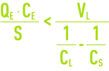
Therefore, for settling to be feasible:
settling tank structure
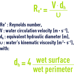
In practice, the ideal settling tank does not exist: turbulence will occur within the liquid, especially in the intake zone and wind can create waves on the surface of the liquid; convection currents created by local temperatures (sunshine) and density differentials will have an effect on clarification performance. Wherever possible, the aim must be to obtain a stable, laminar circulation characterised by an appropriate Reynolds number values established by:
Note: in the case of a full circular pipe, the hydraulic diameter will be the pipe's diameter.
In practice, conditions are deemed to be laminar when Re* < 800.
Furthermore, the Froude number can be used to evaluate circulation process stability when the main influence on the flow is generated by gravity and inertia forces.
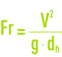
The more stable the circulation, the more even the velocity distribution over the entire tank section and the better the separation. However, stable circulation can be characterised by high Froude numbers.
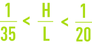
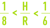
In practice, we can establish optimum H/L or H/R ratios where H is the wetted depth of rectangular settling tanks having a length L or of circular settling tanks having a radius R. Taking a 2-hour contact time, Schmidt-Bregas makes the following recommendations:
- horizontal flow, rectangular settling tanks
- circular settling tanks:
The shape of the structure, the design of the mechanism for supplying raw water and of the mechanism for collecting treated water, as well as the sludge removal mode will all have a significant impact on settling tank performance.
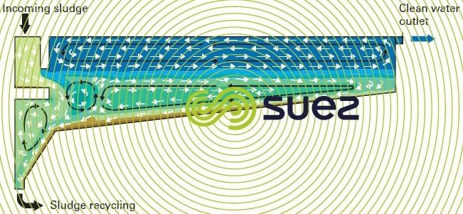
In the case of water or liquor that is heavily loaded with suspended solids, the “density currents” can produce velocity distributions that tend to cause suspended solids that have accumulated on the tank floor to rise in the direction of the recovery channel. This is, for instance, the case of conventional rectangular or circular settling tanks that are too long and that are used to clarify activated sludge (figure 19).
Similarly, the effects of temperature (sunshine, water subject to rapid temperature fluctuations) and disturbances linked to changes in salinity (estuary water, IWW ) will inject variable density water into the settling tank, creating convection currents, even completely overturning the water mass in the settling tank.
Therefore, the ideal settling tank does not exist; nevertheless all these phenomena: stability and/or disturbances can now be modelled and, therefore, viewed and corrected if necessary, using CFD (MFN in French).
Bookmark tool
Click on the bookmark tool, highlight the last read paragraph to continue your reading later
