


classic schemes used
Reading time:We must emphasise that ion exchange processes must only be used after a pre-treatment adapted to each grade of raw water and especially including the removal of suspended solids, organic matter, residual chlorine, chloramines…
co-current line
The old lines comprised co-current regenerated, fixed ion exchange beds: the water to be treated and the regenerating solution percolate from the top downwards through the resin bed.
The complete exchange cycle involves:
- production: an exchanger’s production cycle is defined by the layer’s useful exchange capacity and this is the volume of water treated between two regenerations;
- loosening (or decompaction): a rising water current loosens the resin bed and will eliminate particles and any resin debris that may have accumulated on the surface;
- regeneration: the regenerating solution percolates slowly from the top downwards through the resin layer (co-current regeneration);
- displacement (or slow rinse): water is injected at the same flow rate and in the same direction as the regenerant until almost all the regenerant has been eliminated;
- rapid rinse: water is injected at the production flow rate until the quality of the treated water is such that production can commence.
Description of an ion exchange unit co-current regeneration: irrespective of the nature of the exchange: softening, carbonate removal or demineralisation, each machine usually comprises of a vertical, closed cylindrical recipient containing resin. This machine can be placed in direct contact with the treated liquid collector unit comprising of either nozzles evenly distributed over the floor or a branched manifold. The resin can also by laid over a substrate of inert granular material: silex, anthracite or plastic granules. This layer in turn is drained by the manifold network (figure 80).
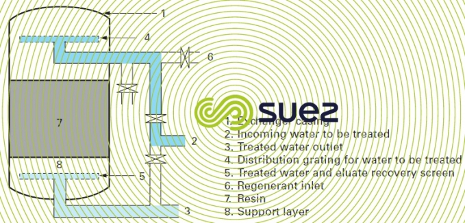

A sufficient space is included above the resin layer to allow the latter to expand normally (between 50 and 100% of the compacted volume depending on the nature of the resin) when countercurrent loosening occurs.
A more or less sophisticated distribution system is used to inject the water to be treated together with the regenerant through the top of the recipient.
Ideally, a regenerant is introduced via a specific regenerant diffuser placed as close as possible to the resin’s highest point. This limits the dilution of the regenerant by the water volumebody before entering into contact with the resin.
The equipment is fitted with an external valve and pipe arrangement used for the various production, loosening, regeneration and rinsing operations.
countercurrent line
Almost all lines currently offered are of the countercurrent type. The first countercurrent systems available during the 1970s and 1980s were of the air or water blocking type. In the present systems, termed blocked bed systems, the resin is held between two strainer floors (without free edges), with a very small space (+/- 100mm) which allows the resin to to swell normally between the regenerated form and the spent form, thereby making it impossible for the resin bed to rise inside the exchanger.
In these blocked bed systems, production can take place either from the top downwards or from the bottom upwards.
Regeneration sequences have been simplified:
- compacting (if required);
- injecting reagents;
- displacement (or slow rinse);
- rinsing and/or recycling.
Therefore, the valve array has also been simplified.
Fines removal and the periodic cleaning of resins is carried out outside the exchanger through hydraulic transfer to a separate column or compartment, see section countercurrent regeneration.
water softening
A cation exchanger is used and regenerated using a sodium chloride solution (figure 81).
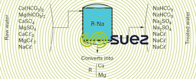
All alkaline earth metal salts (mainly TH) as well as metallic ions alcalino-terreux) in the treated water are converted into sodium salts. Treated water will have almost zero hardness. Its pH and alkalinity remain unchanged. Softening can be carried out after a preliminary purification using lime to eliminate bicarbonates and reduce M-alk. to a level that will usually range from 2 to 4°F. In this case, the water obtained will have had its carbonates removed and will be softened (figure 82).
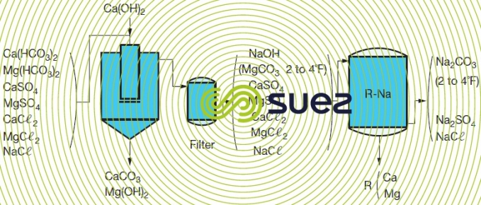
Using lime carbonate removal has the advantage of enabling the water to be treated to be clarified at the same time. For two examples of TSS (following paragraph) carbonate removal using a resin can be an economical alternative to carbonate removal using lime and sand filtration.
carbonate removal
This system uses a carboxylic resin that has previously been regenerated using acid in order to obtain the R-H form (figure 83). This resin has the property of fixing bivalent cations and of releasing the corresponding anions as a free acid until the treated water pH reaches a level of between 4 and 5; this equates to the total release of carbonic acid by the bicarbonates as the cations bound to the strong acid anions (chlorides, nitrates, sulphates) are not fixed by the resin.
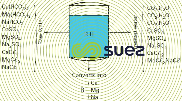
Under these conditions, the treated water contains all the initial strong acid salts and a proportion of dissolved CO2 that is equivalent to the bicarbonates in the raw water. This water may have zero alkalinity and a hardness that is equal to the TH-M-alk. figure for raw water.
Water hardness can therefore be zero if the TH is lower or equal to the level of alkalinity.
If TH is lower than the alkalinity titration curve, the alkaline portion of ions (NaA, K) related to residual akalinty will be fixed by the resin.
Should the contrary occur, zero hardness can be obtained by combining the two or when water titrations allow for this (TH = 1.5 to 3 x alkalinity titration), in the same unit, a layer of carboxylic resin and a layer of sulphonic resin, successively regenerated using a strong acid and a sodium chloride solution can be used deployed . The carboxylic resin operates in an H cycle and fixes TH in quantities that are equivalent to M-alk.. The sulphonic resin exchanges sodium ions for permanent hardness that is equal to TH-M-alk.. This system produces a softened water from which carbonates have been removed.
In the case of water with sodium alkalinity (Alkalinity >TH), carboxylic resin fixing performance becomes poor.
In most cas, it is advisable use a CO2 remover to eliminate the dissolved CO2 released by ion exchange (see section removing CO2) sulfonique, permute.
Where carbonate-free water is used for topping up a cooling circuit, the removal of CO2 can be performed in the cooling tower.
This water may have zero alkalinity and a hardness that is equal to the TH–M-alk. figure for raw water.
Therefore, hardness may be zero when TH is lower than or equal to M-alk. as a preferential exchange will have occurred between the alkaline-earth ions and the alkaline ions. Should the contrary occur, zero hardness can be obtained by combining, in the same unit, a layer of carboxylic resin and a layer of sulphonic resin, successively regenerated using a strong acid and a sodium chloride solution.
The carboxylic resin operates in an H cycle and fixes TH in quantities that are equivalent to M-alk. The sulphonic resin exchanges sodium ions for permanent hardness that is equal
to TH–M-alk. This system produces a softened water from which carbonates have been removed.
In the case of water with sodium alkalinity, carboxylic resin fixing performance becomes poor.
In all cases, it is advisable use a CO2 remover to eliminate the dissolved CO2 released by ion exchange (see removing CO2).
demineralisation
The following description of the most commonly found exchanger groups uses the notation given below:
- WAR: weak acid cation resin;
- ;
- WBR: intermediate or weak base anion resin;
- SBR: strong base anion resin;
- MB: mixed bed.
The section mechanical blocking describes the performance of such systems.
partial demineralisation
SAR + WBR line
This line comprises a unit loaded with a high acidity cation exchanger ( SAR ), regenerated by a strong acid and operating in series with a unit loaded with a low alkalinity anion exchanger (WBR), regenerated by sodium hydroxide or ammonium. The water produced is used as is providing the carbonic acid is not harmful; otherwise, it is degassed through a CO2 remover positioned upstream or downstream from the anionic exchanger (figure 84).
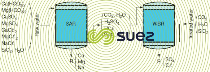
The treated water contains all the silica present and, when degassed by atmospheric air stripping, approximately 10 to 15 mg · L–1 of carbonic acid. Depending on the cation exchanger regeneration level selected, conductivity can vary from 2 to 20 µS·cm–1. A gas membrane treatment may allow CO2 content to be reduced. After CO2 has been removed, pH will be within the 6 to 6.5 range.
This type of line produces water for medium pressure boilers and for some industrial processes.
totale demineralisation
SAR + SBR line
All ions, including silica, are removed (figure 85). In most cases, it is advisable to reduce the flow of ions routed to the anion exchanger by inserting a CO2 remover between the anion exchanger and the cation exchanger. This means that less strong anionic resin will be required and that regeneration reagent consumption can be reduced.
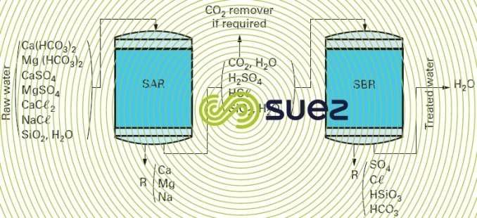
In practice, we mostly obtain water having a conductivity of 1 to 10 µS · cm–1, a silica content of 0.05 to 0.5 mg · L–1 and a pH of between 7 and 9.
This is the simplest scheme and is used to obtain demineralised water that can be used in a wide range of applications.
SAR + WBR + SBR line
This line (figure 86) is a variant on the previous line and produces water of exactly the same quality but is financially attractive when the water to be treated contains a large proportion of strong anions (chlorides and sulphates). Water successively goes through a low alkalinity anion exchanger and a high alkalinity anion exchanger. The carbonic acid remover is optional but can be positioned either between the cation exchanger and the first anion exchanger or between the two anion exchangers.
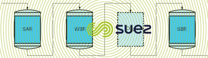
Anion exchanger regeneration is carried out in series with the sodium hydroxide solution going through the high alkalinity resin first and then through the low alkalinity resin. This method produces considerable sodium hydroxide savings compared with the previous method because, in general, the excess sodium hydroxide generated by high alkalinity resin regeneration using a normal amount of sodium hydroxide will be enough to wholly regenerate the low alkalinity resin. Additionally, when raw water contains organic matter, the low alkalinity resin will protect the high alkalinity resin.
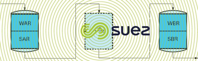
Lines using the WAR + SAR and WBR + SBR group
This group is of interest when the water contains a significant proportion of bicarbonates. Regeneration takes place in series, passing through the sulphonic exchanger and then the carboxylic exchanger.
As carboxylic resin regeneration takes place almost stoichiometrically from the excess free acid remaining after the sulphonic resin has been regenerated, the overall regeneration level drops considerably.
Figure 87 shows a system that provides for minimum reagent consumption (clearly, in countercurrent regeneration mode).
demineralised water quality
The quality of the demineralised water will mainly depend on the cation exchanger regeneration rate.
In effect, any ion leakage from the cation exchanger will be converted into a free base (NaOH) at the anion exchanger generating a silica leakage from the anion exchanger. Therefore, a polishing system must of necessity include a cation and an anion in separate or mixed beds.
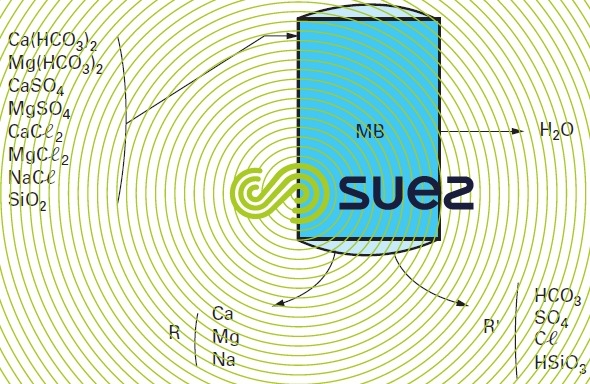
mixed beds ( MB )
The main difference between this process and the separate bed solutions is the fact that two strong resins, cationic and anionic, are enclosed in the same unit. These resins are thoroughly mixed together. Resin grains thus laid side by side will behave like an infinity of cation and anion exchangers in series (figure 88).
For regeneration purposes, both resins are hydraulically graded during the loosening phase. The lighter anionic resin rises to the top and the heavier cationic resin falls to the bottom.
When the resins have been separated, each will be regenerated separately using caustic soda and a strong acid respectively. The excess regenerant will then be removed by rinsing each bed. When the machine has been partially emptied, compressed air is used to mix the resins. Rinsing is completed and the machine ready to embark on the next cycle.
Mixed beds have the following advantages over separate beds:
- production of extremely pure water of a quality that remains constant throughout the cycle (conductivity below 0.2 µS · cm–1, silica below 10 mg · L–1);
- pH close to neutral.
Mixed beds have the disadvantage of a lower exchange potential and of not being so easy to control because of the need to achieve perfect resin separation and mixing.
Mixed bed exchangers can be used direct on water providing this water only has a low mineral content (water that has first been treated using reverse osmosis or distillation, condensed water, closed circuit nuclear pool water…). It is possible for one single mixed bed to replace a complete ion exchanger system.
However, mixed bed exchangers are mainly used in finishing treatments and, in this case, because of the low incoming ionic load, they are only regenerated every 5 to 10 cycles of the primary system.
Installation including a separate bed finishing line
This line can take the for of two columns in series, SAR-SBR; regeneration can be carried out in series with the exchangers for the primary line in order to save on regeneration reagents.
Thus, we obtain a conductivity that is below 0.5 µS · cm–1 and a silica content of between 5 and 20 mg · L–1.
However, this system is used less and less. It has been overtaken by mixed bed exchangers that produce a better quality (see above).
For some applications, for finishing, we can make do with a low or high acidity cation exchanger used to neutralise the soda leak from the primary line anion exchanger. This finishing exchanger is used to obtain water that is virtually cation-free (conductivity below 1 µS · cm–1) with a 6 to 7 pH.
Bookmark tool
Click on the bookmark tool, highlight the last read paragraph to continue your reading later
