


clarification
Reading time:Clarification refers to the sequence of operations used to remove suspended solids(mineral and organic) from the raw water together with a proportion of the dissolved organic matter ("flocculating"fraction).
Depending on the concentrations of the various contaminants present, there may be the need for increasingly complex operations ranging from simple filtration with or without reagents to coagulation – flocculation – sedimentation or flotation – filtration.
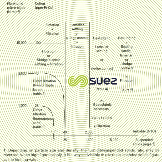
Referring to the classification provided in figure 2, a few typical examples of the most representative solutions are provided below. The reader is also reminded that the systems described will be followed by polishing treatment if necessary (see polishing: removal of organic matter and micro-pollutants) and, in all cases, by disinfection (see disinfection).
filtration without reagents (figure 2 – line 2)
When the raw water only contains relatively few, non-colloidal, suspended solids (as is very rarely the case with surface water), treatment will then consist ofdirect filtration without reagents, possibly following pre-oxidation (chlorine, ozone) if necessary. As noted previously, pre-chlorination is increasingly being dropped in favour of pre-ozonation and the ozone pre-oxidation step is usually combined with coagulation. In general, filtration without reagents is no longer an option in countries governed by European or WHO standards, except in the special case of slow filtration (see section background and general features).
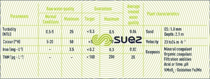
At present, the effectiveness of membranes has led water specialists to increasingly recommend ultrafiltration membranes instead of sand or dual media filtration. Rouen (France) (1,000 m3·h–1) constitutes the perfect example: processing karstic water and despite major quality variations (1 to 150 NTU), the treated water turbidity always remains below 0.1 NTU and this is achieved without the need for coagulant addition (figure 3).
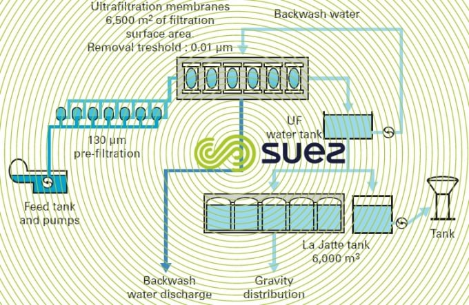

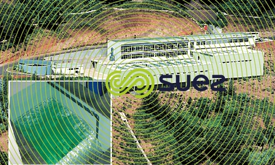
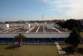
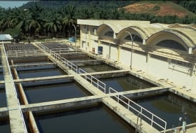
This type of plant (photo 3) is perfectly adapted for a karstic water source, lake water supply and limited capacity as it produces water that always satisfies the most stringent microbiological and turbidity standards without the need for highly qualified personnel on site. Easily automated, these systems are controlled by a turbidity meter and can automatically transfer from dead-end filtration (normal operation withlow turbidity) to tangential filtration (during turbidity peaks), see Membrane separation, systems using clarification membranes and ucd (Degrémont)® compact unit).
coagulation, followed by filtration (figure 3 – line 3)
In the case of raw water having a slightly colloidal turbidity and/or slight colour and/or containing no more than 1,000 to 2,500 micro-algae per mL (therefore close to the A1 quality grade defined by French decree 2001-1220), based on the preceding scheme, a coagulant and, if necessary, a flocculant are utilised. Low dosages should be used as these reagents will shorten the filtration cycle length between successive backwashes. The coagulant will be used to remove a certain proportion of organic matter. However, it must be noted that water that is slightly turbid but highly coloured or laden with algae, cannot be properly treated using this approach: instead a higher dosage of coagulant will be required and therefore, a sedimentation or flotation stage will need to be included.
This apparently simple technique can have a number of application variants, using single or multi-media filters.
coagulation on filters
Also called contact filtration(or in line filtration), this design is the easiest to use: the coagulant is injected in line (static mixing…) without any coagulation or flotation stage. In some cases, especially with cold water, a flash mixer can be added between reagent injection and filtration; water then arrives at the filters in a coagulated state but flocculation is only completed as the water percolates through the upper layers of filter media (sand…).
Examples can be provided by Asseiceira (Lisbon, Portugal), 500,000 m3·d–1 (see the section neutralisation and/or remineralisation figure 44) and Roberval (Canada), 9,600 m3·d–1 where pre-oxidation using ozone plays an essential role (figure 4); in effect, in this latter example, use of pre-oxidiation will:
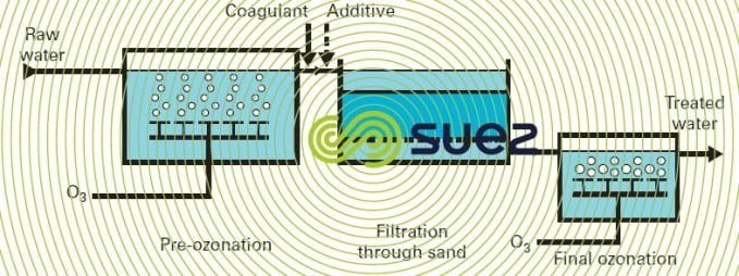
- destroy the organometallic complexation binding iron and/or manganese to the organic matter;
- oxidise any iron and manganese present if the organic matter concentration is not too high;
- form a floc that can be removed through filtration.
flocculation-filtration
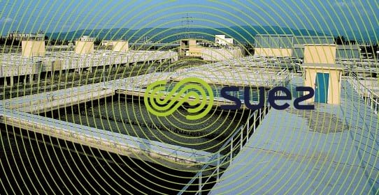
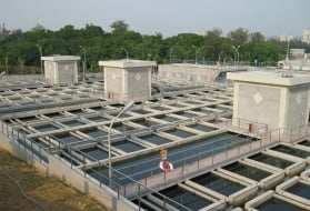
In the case of direct filtration after flocculation, filtration will be preceded by one or more flash mixers (with a contact time in the range of one minute) and one or more contact basins acting as either a flocculator or as an intermediate reactor ensuring the necessary time intervals between reagent additions (e.g. Sydney plant; photo 4) - see also section filtration through a granular bed and aquazur sand filters)
This type of plant must be particularly recommended for direct filtration of all water since the water temperature is likely to fall below 10°C and/or in cases calling for several reagents.
Nevertheless, in order to optimise the different treatment parameters, longterm pilot trials may be required for the purpose of determining:
- the optimal metallic salt and/or organic coagulant (depending on local regulations);
- the optimum pH;
- in frequent cases, the optimal organic additive for enhancing floc filterability;
- the effective size of the filtering medium (media);
- the filter media depth;
- and the maximum velocity.
This makes it possible to provide guarantees that are difficult to achieve as illustrated in table 2 (results achieved with the Sydney plant).
double filtration
This treatment approach features two filtration steps in series: the first using a high ES material (sand or biolite) that acts as a roughing filter for the second filter which is designed using a fine material (sand) or a dual media configuration. This technique is used to process higher loading water without settling (thereby using fewer reagents), an acceptable approach for single stage direct filtration. This applies to the Alegria plant in the Azores (photo 5); however, organic matter elimination is less satisfactory as compared to a comprehensive clarification-filtration treatment approach.
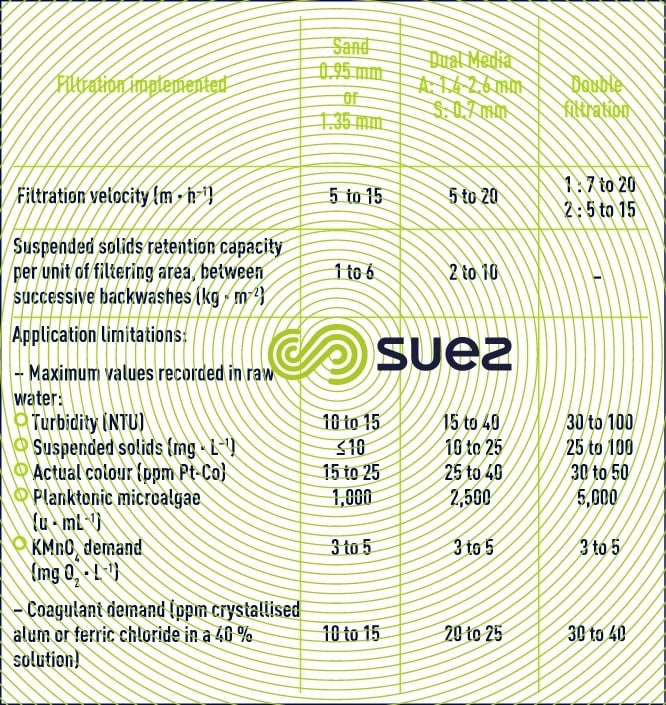
direct filtration procedures and utilisation limits
Table 3 presents the maximum figures indicated for the various raw water criteria; the following can be taken into consideration:
- the first figure applies when all adverse properties exist at the same time;
- the second figure applies when the parameter examined is the only one affected and when it only represents a limited duration peak value.
When these maximum figures represent a virtually continuous characteristic of the raw water, then preliminary testing becomes necessary.
complete clarification treatment (figure 2 – line 4)
This treatment approach must be applied to all waters where turbidity, colour, suspended solids, algae and oxidability properties exceed the figures quoted in table 3 without, however containing significant pollution (close to the A2 quality according to French decree 2001-1220, appendix 1 – 3).
systems comprising sedimentation
These systems are by far the most frequently used type of treatment: solids-liquid separation via settling (sedimentation) occurs following the addition of coagulation-flocculation reagents and before filtration, thereby eliminating most of the floc and thus allowing filters to operate normally.
a) When the suspended solids level in the raw water is consistenly below approximately 1 to 2 g · L–1 (depending on particle size), one can opt for sludge contact and/or lamellar clarifiers after a suitable pre-treatment (see bar-screening-straining) as was done for the Algiers (Algeria) plant (540,000 m3·d–1) that has six Pulsatube clarifiers and Aquazur V filters (photo 6).
b) when suspended solids are likely to exceed 2 g·L–1 during at least part of the year:
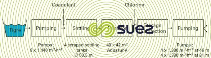
- from 2 g · L–1 to 5 g · L–1: depending on the case, one can use either a single stage static settling tank with scraper (velocity between 1 and 2 m · h–1) as for the Mossul plant in Iraq (207,000 m3·d–1) (figure 5), or a desludger (see section static settling tanks) followed by a static or lamellar or solids contact clarifier.
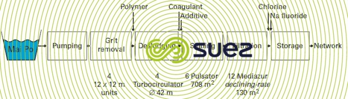
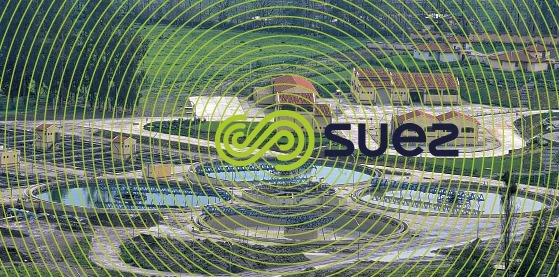
- over 5 g · L–1: a single clarifier could become overwhelmed by an excess sludge flow and this is when two-stage clarification becomes compulsory, as in the case of the La Florida plant in (Chile) that includes a pre-clarification -desludging stage (in this case using Turbocirculator) followed by a main clarification stage (Pulsator) (figure 6 and photo 7).
However, this range is also subject to an upper suspended solids content limit beyond which the reagent demand becomes prohibitive and the volume of sludge produced far too high to be extracted and, therefore, incapable of generating a sufficient amount of clear water. In general, it becomes very difficult to run a plant when the suspended solids in the raw water rise above 40 to 50 g · L–1 (as some waters can have peak suspended solids contents of almost 200 g · L–1). In this case, one needs to carefully evaluate the raw water flow rate required to produce a given output of treated water and the resulting sludge flow to be extracted: in effect, the sludge concentration obtained from this heavily loaded water will fluctuate from less than 100 g · L–1 to greater than 400 g · L–1, depending on the type of suspended solids and on the treatment applied. If necessary, a raw water storage tank can be installed upstream of the plant to deal with periods of high loading.
A desludger (see appliance types in the section lamellar settling tanks) will run with a hydraulic loading of between 1.5 and 10 m3·h–1·m–2, depending on the suspended solids loading and the chemical treatment regime used. In order to be effective, this type of equipment must not be regarded as a grit removal unit: when grit is present in significant quantities, a preliminary grit remover (see section area of application), having a removal capacity of 0.15 to 0.3 mm must be included in order to avoid damaging the scraper mechanism.
Whenever a plant has two clarification stages, it is advisable to implement the double flocculation technique (injecting reagents upstream from each clarifier) as this can sometimes generate significant savings. This double flocculation should be implemented according to conditions adapted to each case, based on the type and maximum suspended solids levels forecast:
- in lighter loading water, double flocculation may simply consist of dividing the amount of metal salts coagulant between preliminary clarification and main clarification;
- in waters where the suspended solids are in the 5 g · L–1 range, the best result is often achieved by using a cationic polyelectrolyte in the desludger. For instance, in a Costa Rica plant: where the raw water suspended solids can quickly fluctuate between 50 mg · L–1 and 5 g · L–1 continuous injection of 1.5 g · m–3 of a given polymer into the desludger, operating at a speed of 3.5 m · h–1, resulted in a very stable pre-clarified water quality and made it possible to maintain the the alum dosage to the Pulsator used for the main clarification between 30 and 40 g · m–3;
- in the case of highersuspended solids levels (10 g · L–1and above): an anionic polymer has to be injected at the inlet and the desludger must be designed as if it were a sludge thickener.
In all cases, the purpose of the first treatment stage is not to obtain the perfect quality water; in effect, the downstream clarifier will often be more effective on a medium loading water (200 to 500 mg · L–1) than on water that contains little suspended solids (< 50 mg · L–1).
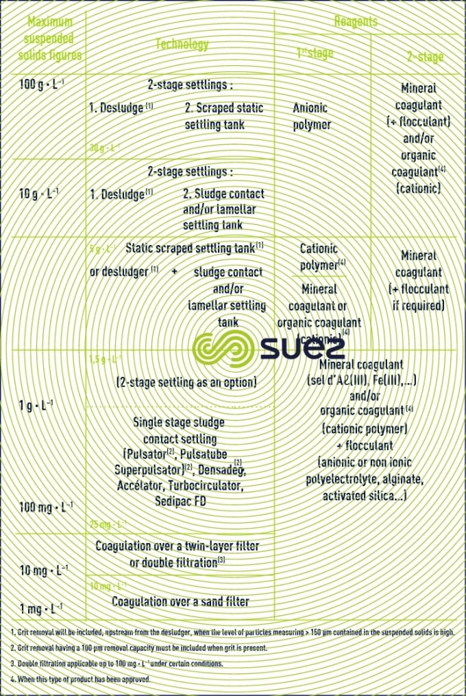
Table 4 summarises the selection criteria used as the basis for the design of a multi-stage clarification system according to the suspended solids content in the raw water.
flotation
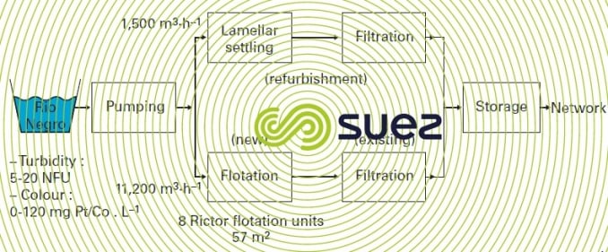
During the 1960’s, flotation was developed in Scandinavia in order to supply towns with drinking water and some industries (especially paper mills) with process water, using water from lakes that are generally cold, coloured but not very turbid.
From the 1970’s, this technique was widely used, in various other countries (England, Belgium, France, South Africa…) to process surface water with a low clay loading but, however, high in algae, colour, humic acid or other organic matter (please refer to the two examples shown in photo 8 and figure 7).
This technique tolerates :
- high speed solids-liquid separation (7 to 35 m · h–1 depending on the specifictechnology used, see section flotation units);
- great operating flexibility (easily shut down and restarted);
- minimal amounts of flocculant reagent.
Therefore, the preferred case for applying this technique is wherethe water regularly has an algae content greater than 2,500 organisms per mL and/or colour exceeding approximately 40 ppm Pt-Co, while never exceeding turbidity levels of 40 NTU or suspended solids contents of 25 to 30 mg · L–1 (unless high levels are transient and where easy flotation unit cleaning methods have been included).
However, one must remember that:
- dissolved air flotation consumes more energy than sedimentation (40 to 80 Wh · m–3 of water as compared to less than 10 Wh · m–3 for most settling clarifiers);
- this process will not tolerate any pressurization circuit mechanical failure.
summary of clarification treatments
The following diagram (figure 8), recaps the key points of this sub-chapter, and can be used as a tool for designing a clarification system according to turbidity, suspended solids, colour and planktonic micro-algae concentrations.
Bookmark tool
Click on the bookmark tool, highlight the last read paragraph to continue your reading later
