


attached growth processes
Reading time:the biological film
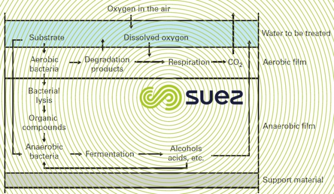
Most micro-organisms can colonise the surface of a substrate when they are at the growth stage. Bacteria attach themselves to the substrate by means of the exopolymers they produce. The initial colonisation of a solid takes place on a number of preferential sites and it is from these sites that the biofilm develops until the total surface area of the substrate is coated., At the same time, new cells are produced and cause the film to thicken.
The oxygen and nutrients carried in the water to be treated diffuse through the film until it achieves a thickness such that oxygen no longer reaches the deepest cell layers. Thus, stratification occurs in thick films with the superimposition of an aerobic layer within which the oxygen diffuses and a deeper anaerobic layer that contains no oxygen. The size of these two layers will vary depending on reactor and substrate types (figure 32).

Using biofilm processes in water treatment has shown that:
- the rate at which the substrate is depleted stabilises at a constant level once the biofilm thickness is such that oxygen becomes a limiting factor in the deepest layers;
- in aerobic films, attached bacteria usually have a level of specific activity that is higher than that observed in suspended growths.
Based on this principle, various so-called attached growth processes have been evolved; some are quite old, others more recent. They can be separated into three categories: non-submerged attached growth processes (trickling filters), submerged attached growth processes (biological filters or biofilters) and combined processes that use fixed or mobile support matter.
bacteria beds (or trickling filters)
operating method
The trickling filters operating principle consists in trickling water that needs to be treated, after it has undergone primary sedimentation or at least been thoroughly screened, through a mass of matter (natural or plastic) acting as a substrate to purifying micro-organisms that form a thick film on this substrate.
Attached micro-organisms remove organic matter by absorbing its soluble and suspended constituents. As the micro-organisms grow, the film becomes thicker and we observe a two layer film: aerobic and then anaerobic. In this second section, endogenous mechanisms and the gas produced cause the biofilm to lift off locally creating new zones where new colonisation can take place. This biofilm separation phenomenon or "sloughing" is mainly dependant on the organic and hydraulic loadings applied to the filter.
The oxygen required for aerobic metabolism to take place will be supplied by natural draughts or forced ventilation.
The liquid collected at the film outlet feeds a secondary sedimentation tank where the sludge produced is separated from the treated water. A proportion of the liquid collected is often recycled to the trickling filter inlet where it dilutes the influent and ensures that the biofilm is kept sufficiently wetted. Trickling filters were the main biological purification process used during the 50’s and they do have a number of advantages over activated sludge systems:
- they require less monitoring;
- they produce a noticeable energy saving (no air injected);
- they "recover" quite quickly after a toxic shock.
However, they suffer from a number of drawbacks:
- for the same BOD loading, trickling filters are far less efficient at purification;
- they run the risk of clogging, especially in the case of traditionally filled beds (3 cm Pozzolana);
- they are expensive to construct;
- in general, sludge is not stabilised;
- danger of nuisances (flies, odours…).
classification
Trickling filters are classified according to the hydraulic and organic loadings applied. Hydraulic loading is expressed in m3 · m–2 · h–1 in relation to the filter’s cross section, inclusive of recirculation flow rate.
The organic loading is normally expressed in kg BOD · m–3 · d–1 in relation to the volume of matter but also, in particular, with regard to the nitrification application, in kg BOD · m–2 · d–1 or in kg N-NH4 · m–2 · d–1 in relation to the material’s developed surface area.
Trickling filters classification is given in table 8, according to the hydraulic or organic loading applied.
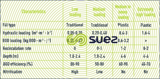
The main information gleaned is as follows:
- low rate trickling filters are used with shallow matter depths (1 to 2 m) and usually with traditional fillers. Under favourable conditions (climate, influent properties), they will produce a properly nitrified, low BOD discharge. This type of BOD loading can also be used in tertiary nitrification with a plastic filler;
- medium rate trickling filters use one or two stages, depending on target performances, with hydraulic recirculation. In order to prevent the matter from clogging as the result of excessive biofilm growth, we need to operate with a minimum hydraulic loading that can vary according to the type of wastewater and the nature of the matter selected. The instantaneous, continuous or intermittent hydraulic loading must fall between 1.8 and 3 m3 · m–2 · h–1. Recycling is usually required, either immediately at the trickling filter outlet or more rarely after the downstream sedimentation tank.
- high loading beds are mainly used when coarse screening concentrated water (especially industrial discharges) before submitting it to a secondary treatment. Their main advantage is that their energy consumption is low per kg of BOD removed.
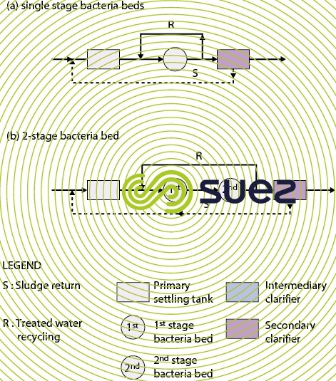
Figure 33 illustrates different application configurations. However, consideration can also be given to other schemes combining bacteria beds and activated sludge treatment systems.
general provisions
Trickling filters installation design involves several elements: packing material, hydraulic distribution mechanism, aeration system, downstream protection and clarification.
packing material
The ideal packing material must provide an extensive contact surface area, a high void space and adequate mechanical strength. Table 9 details the materials used together with their properties.
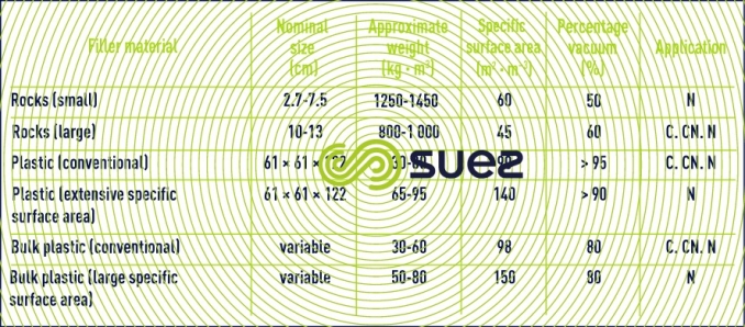
We can distinguish between:
- traditional packings: Pozzolana, metallurgical coke or crushed siliceous pebbles. Their low void space (~ 50%) creates a risk of rapid clogging and restricts the organic loading that can be applied. Nowadays, they are rarely used;
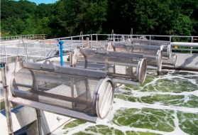
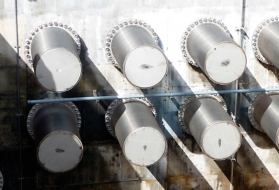
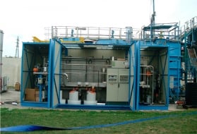
- plastic packings (photo 4): commercially available materials meet the following requirements: sizeable specific surface area of between 80 and 150 m2·m–3, void space index, often better than 90%, lightweight and with sufficient mechanical strength enabling these materials to be used in depths of 4 to 6 m. It should be noted that under normal service conditions, charged with zoogloea, the material can weight between 300 and 350 kg · m–3. These types of packing can differ in terms of shape, honeycomb structure and by the nature of the basic material used (PVC or polypropylene).These materials can be supplied as a structured system, i.e. in the form of parallelepiped modules, or in bulk. Bulk materials are more sensitive to clogging and their use will be restricted to diluted water that has low suspended solids loading.
In the case of structured materials, modules will be stacked up to a certain height in circular or rectangular towers with a lightweight external structure; plastic fillers are self-supporting. The material must be laid over a grating or a system of beams. Great care must be taken when designing this support structure because it is here that bed clogging can often start.

hydraulic distribution
Water to be treated, including recirculation water, is distributed to the top of circular filters by a rotary distributor made up of between two and six arms mounted on a central pivot that rotates horizontally. These arms consist of perforated tubes through which water is delivered over the filter. The distributor is actuated either by being propelled by the water delivered through its holes for the plants with a size smaller than 10,000 PE, or, by a variable speed motor for others plants.
For rectangular trickling filters, fixed distributors or a combination of fixed and rotating distributors can be used for distribution purposes.
One of the main parameters ensuring that a filter operates satisfactorily is the spraying rate (SK factor in German), i.e. the depth of the liquid released over the material each time the spraying arm crosses the material (in mm/pass).Experience has shown that the spraying rate has a major effect on material sloughing and, consequently, on biofilm thickness and on the trickling filters’s purifying performance. The distributor’s design must be such that its speed of rotation and spraying rate can be adjusted according to the BOD loading; in particular, high intensity intermittent spraying (flushing effect) must be included on medium to high loading filters.
aeration system
An appropriate air flow is essential if aerobic conditions are to be maintained in a trickling filters and, therefore, if we are to achieve satisfactory performance levels and no odours.
Historically, air was supplied by "natural draughts" through openings made in the base of the bed: providing there is sufficient free passage, the temperature differential between the ambient air and the air within the bed will create air circulation that will often provide enough aeration. However, in some countries, especially in summer, during certain times of the day, low temperature differentials will mean that there will not be enough air circulation. Forced ventilation using blowers will be recommended in such cases in order to provide a reliable source of oxygen and to avoid odours.
protection
Protection measures specific to this process will be required:
- against cold. Plastic trickling filters behave like cooling towers. In cold countries, we recommend limiting heat losses through the use of twin cladding and a roof in conjunction with regulated ventilation;
- against corrosion special care must be paid to protecting metal parts, especially in the distribution zone and on the support floor;
- against nuisances. In the treatment of certain industrial effluents (breweries, distilleries…), trickling filters can be the source of noticeable odours. These bacteria beds will have to be covered and, occasionally, draught air will have to undergo odour control;
- against insects (flies, mosquitoes): cover (at least a fine mesh net) and especially intensive spraying (see SK).
clarification
Suspended solids that separate from the support media (excess sludge) are recovered in the secondary sedimentation tank, producing clarified effluent. This system has two main differences from activated sludge clarifiers: the suspended solids infeed concentration is markedly lower and sludge recirculation is pointless (save in exceptional cases when it will, however, remain low).Maximum velocities of approximately 1.5 m · h–1 will produce suspended solids contents of less than 30 mg · L–1.
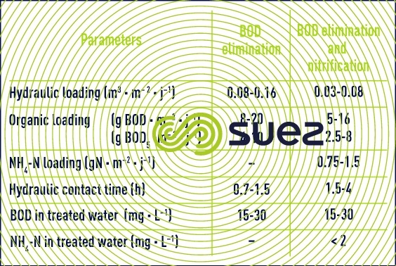
Biological processes details the main applications and performance levels for these filters.
biological filters (or biofilters)
presentation and background
A bacterial culture’s activity will specifically depend on its exchange surface area (substrate and oxygen).In activated sludge, this surface area will be limited because of flocculated micro-organisms. In trickling filters, the developed area of the support medium per m³ of reactor remains low and achieving the ideal distribution of water to be treated over the entire biofilm can be problematic on an industrial scale. Additionally, the biofilm is thick and has major diffusion limitations.
Whence the idea of attaching micro-organisms to granular support media having an effective size of less than 4 or 5 mm, producing a specific developed surface area and, therefore, an exchange surface areas far greater than that found in other processes. For instance, the biolite material having a 2.7 mm effective size develops an exchange surface area of 700 m2 · m–3 compared with 100 to 200 m2 · m–3 for a trickling filters with plastic filler.
This consideration led to the development, over the past three decades, of attached growth processes called biofilters. Please refer to figure 34 for their method of operation.
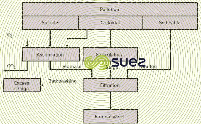
These processes comprise three phases: contact material and its biofilm, liquid and air. BOD and/or N-NH4 in the liquid phase is oxidized when it comes into contact with the biofilm. Oxygen is supplied by injecting air into the material or by pre-dissolving it in the feed water.
Fixed bed processes include upflow or downflow reactors depending on the water's direction of passage. As anticipated, the type and granulometry of the fill material are major factors with regard to the performances and operating characteristics of these reactors,
These processes do not require clarifiers. Excess sludge created by the retention of the influent’s suspended solids and by biomass growth is trapped in the system and has to be removed at regular intervals by a wash carried out within the reactor itself.
Used above all as aerobic filters, these processes can also be applied as anoxia filters for denitrification.
There are different types of biofilters. The following two paragraphs provide a selection of the most commonly found processes.
aerobic filters
Aerobic filters are used in the following applications: for removing carbon, for removing carbon combined with nitrification, tertiary nitrification and polishing treatment. Their dimensioning is based on both the BOD loading (expressed as kg of BOD · m–3 of material · d–1 or as kg N-NH4 · m–3·d– 1) and the filtration rate (expressed as m3 · m–2 · h–1 or as m · h–1). The latter will vary noticeably depending on the type of material and the direction of flow of the water to be treated. The same applies to oxygenation efficiency which is indicative in a biofilters of the percentage of the oxygen mass that has actually been transferred to the system (i.e. under actual operating conditions) compared with the mass of oxygen injected.
Because of its principle, the biofilter is sensitive to the influent's suspended solids concentration and should be used preferably after primary sedimentation (whether or not physical-chemical) or on diluted water.
When a carbon and nitrogen treatment is required, the choice to be made will be between a single stage (BOD5 removal and nitrification) or a two stage system (BOD5 removal followed by nitrification).The influent’s BOD5 concentration will have a direct impact on the N-NH4BOD loading removed because the heterotrophic biomass will be competing with the autotrophic biomass for oxygen (as discussed in the case of activated sludge). The following factors are the main ones that will influence the technical-financial choice to be made between these two systems:
- properties of the influent to be treated (BOD/TKN ratio, BOD concentration);
- required nitrification performance (partial or thorough nitrification);
- installation capacity.
From a biological viewpoint, the two stage system is preferable because separating the two functions and, therefore, the two biomasses, means that permissible loading and the performances of each stage can be optimised and we can use an optimum backwashing cycle for each of the two stages.
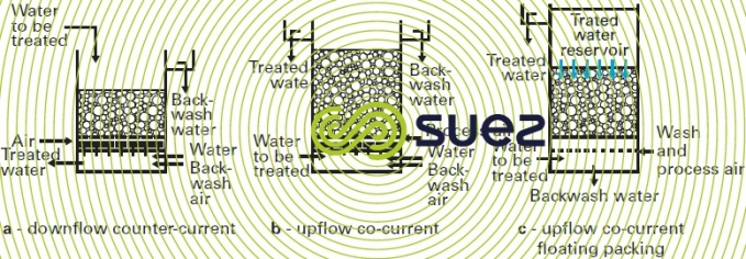
downflow filters
The first biofilter which appeared on the market at the beginning of the 1970s was the Flopac. The Flopac is a downflow filter for which the water to be filtered is saturated in oxygen upstream of the filter. The filtering material of the first filters, known as chamotte, was produced by firing clay injected with organic matter, permitting a granular material with a specific high surface to be obtained. Chamotte was replaced a few years later by sand and / or biolite.
upflow filters
The Biofor is an upflow biofilter where co-current process air and water is injected via a network of fine bubble diffusers called Oxazur. Biolite is the filtering medium; its granulometry and density (always better than 1.2) are selected according to the application (figure 35-b).
During recent years, various improvements have been made to Biofors which helped to improve its performance. Operating criteria, applications and performance provided by this latest generation of Biofor are detailed in the chapter Biological processes.
More recent upflow filters made from a synthetic material with a density of less than 1, are now available on the market. The floating matter is retained by a ceiling equipped with nozzles (figure 35-c).
In principle, this reactor can be used in nitrification only applications or in combined nitrification-denitrification applications. Process air is injected either into the base of the bed (N filter) or into the material (combined N/DN filter).
The treated water is stored above the filtration bed and used for sequenced backflow washes; during this stage, the injection grating continues to be supplied with air in order to increase the mixing energy.
The Biostyr is well suited to nitrification of water that only has a light suspended solids loading; however, this system is more limited use in eliminating carbonaceous pollution due to the danger of the material becoming fouled. However filters can be used for denitrification.
anoxic biofilters
Biological filters can also be used in denitrification, combined with a suspended or attached growth secondary nitrification treatment. The main differences between aerobic and anoxic filters are the absence of a process air system, the material’s size and the input of external carbon if required.
Constituting a perfect analogy with regard to activated sludge nitrification-denitrification schemes (same principles, same limitations), the denitrifying filter must be positioned either up or downstream from the denitrification treatment.
- upstream denitrification (or pre-anoxic): the nitrifying stage is located downstream, with nitrate recirculation. Denitrification performance will depend on the recirculation rate, on the rapidly biodegradable COD and, therefore, on the influent’s COD/TKN ratio:
- downstream denitrification (or post-anoxic): in the absence of any biodegradable organic carbon consumed by the upstream aerobic system, an external source of carbon, methanol or acetate will need to be included.
biofilter performances and areas of utilisation
Given their modular nature, biofilters can be used in a variety of ways in "exclusively biofilter" type treatment systems or in combination with suspended growths.
Examples of these systems combining primary sedimentation (PS), even physical-chemical sedimentation (PS-PC) with suspended growths (AS) and/or C (carbon only), C+N (carbon + nitrification) and DN (denitrification) biofilters whether or not combined with phosphorus removal (P) are provided in figure 36).
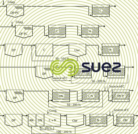
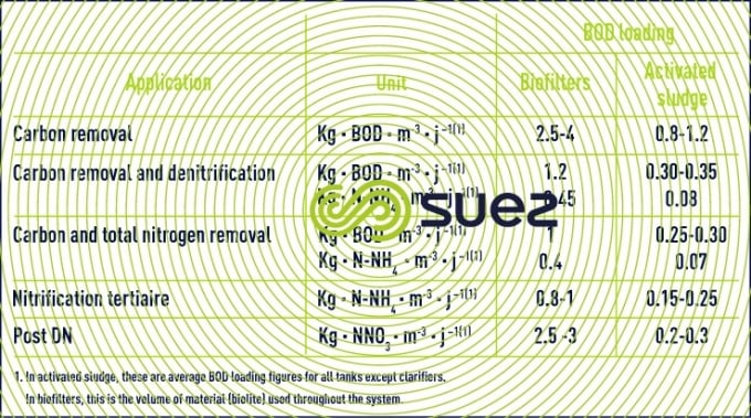
Furthermore, based on the target treatment objective, it is interesting to compare overall permissible BOD loadings in a typical water, between "exclusively biofilter" and activated sludge systems.
Table 10 highlights the major interest provided by attached growths in terms of BOD loading to which can be added other advantages associated with their operating principle:
- low ground surface area (high biomass concentration and high BOD loading);
- no clarifier and, therefore, no sludge clarification problem;
- great stability in the face of fluctuating loading;
- capable of processing diluted and cold water;
- easily integrated on site (visual appearance).
The downside is a relative amount of complexity in terms of automated controls and instrumentation, an investment cost that is higher than that for activated sludge (except when faced with exceptional environmental limitations) and the need to manage large biofiltration plants in the same way as surface water filtration plants (sand and/or GAC filters); preventive maintenance on valves, monitoring head losses after washes.
other processes
Several technologies have been put forward in an attempt to achieve a compromise between attached growths and activated sludge in order to maintain the value of the former: keeping a large amount of biomass in the aerator; this biomass does not pass through the secondary sedimentation tank, enabling us at the same time to overcome the minimum sludge age required for nitrification and to maintain high kinetics. Of these, we should quote combined growth, rotating biological contactors and submerged fixed film processes.
combined growth processes
Various processes exist during which a support material is suspended in an activated sludge aeration basin.
These materials, which have a similar density to water (from 0.95 to 1) and are modest in size (from a few milimeters to about 20 mm), can be suspended in the basin for as long as sufficient stirring is maintained. Given their large specific surface area (more than 1000 m2/m3 for certain applications), they are capable of supporting a significant fine film of biomass (at least on the outside of the matter) and, therefore, reduce the size of the tanks required. In every case, in order to guarantee good functioning, it is essential to provide for:
- a fine screen to avoid fibres clogging grills;
- retention grills systematically positioned on the outlet flow of all of the reactors containing mobile supports (meshes according to support geometry);
- an adapted basin form and aeration design in order to avoid an accumulation of supports at the level of retention grills.
Two implementation configurations can be envisaged :
- Meteor IFAS (Integrated Fixed film Activates Sludge ): It consists in the association of an activated sludge (free culture) and a fixed culture on a mobile support
- Meteor MBBR (Moving Bed Biofilm Reactor): In this configuration, the totality of the active biomass is fixed on mobile supports. Conventional settling is not adapted for the separation of suspended matter ; a flotation type separator must be used (rapid flotation, of the Greendaf type for example). No recirculation is implemented and there is no accumulation of free biomass in the reactor.
Meteor IFAS
In this configuration, the support material is introduced in the reactors to the order of 450-60% on average and coupled with a conventional separation system (clarifier). No particular specification is necessary.
This process will be equivalent to a standard activated sludge process in terms of performance. The Meteor IFAS applies to the same types of raw water as conventional activated sludge ; the gain occurs at the level of dimensioning insofar as the biomass density will be higher than for a conventional activated sludge solution. It will namely be adapted in the event of the rehabilitation of a facility affected by surface constraints, an increase in load (carbon and nitrogen) and / or a stricter discharge quality objective.
Meteor MBBR
In this configuration, the fill rate is identical to the Meteor IFAS solution, at an average ofbetween 450 and 60%.
The Meteor MBBR permits an elimination of carbon and nitrogen pollution with high loads. For separation, given the nature of the biological floc, it will be obligatory to provide for rapid flotation of the Greendaf type. As the biomass is fixed on the supports, no recirculation is implemented which means that there is no accumulation of free biomass in the reactor. This process can be applied in the case of urban and industrial effluents.
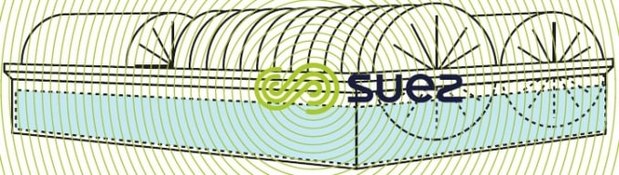
rotating biological contactors (RBC)
This technique was first used in West Germany in 1960. It consists of a series of fairly closely packed circular discs that are partially submerged (usually 40%) in the water to be treated and rotate round a horizontal axis. The rotary movement means that the biomass that develops on the contactors will alternately come into contact with the water to be treated and with the oxygen in the air.
A reduction gear is used to rotate the contactors. Some installations include assisted rotation and oxygenation though additional air injected beneath the scoops that form an integral part of certain contactors. The polystyrene or PVC contactors are supplied in standard sizes with diameters of up to 3.66 m, and the length of the axis bearing the discs can reach 7.62m. Standard discs have a developed surface of approximately 9 300 m². The specific surface is of approximately 175m2/m3. They are set at 2 to 3 cm intervals and their speed of rotation is between 1 and 2 rpm (figure 37).
Similar to trickling filters, biological rotating contactors require pre-treatment, primary sedimentation or fine screening as well as a final clarifier for screening out excess sludge and designed to take a maximum upflow velocity of approximately 1.5 m · h–1. This system does not use sludge recirculation.
There are other similarities between biological rotating contactors and trickling filters. The complexity of the physical and hydrodynamic characteristics means that their design has to be based on criteria produced from pilot studies and industrial plants. The organic loading applied affects the BOD removal performance and thorough nitrification requires a low residual BOD.
Systems often incorporate several rotating contactor stages, the first being used to remove organic carbon, the latter for nitrification. Loadings are expressed as g of BOD5 or as g of N-NH4 per m² of rotating contactor area and per day.
Table 11 lists typical design criteria. This technique has the advantage of low electricity consumption (2 to 4 W per m² of contactor) but has not become widespread because of:
- the need to stabilise primary and biological sludge;
- extra investment required for a target treated effluent containing less than 25 mg · L–1 of BOD;
- some mechanical problems (drive mechanism);
- the need to cover the rotating contactors to protect them against weather conditions.
This technique is mainly suitable for small plants where the low loading choice means that the drawbacks referred to above can be limited and that very simple maintenance systems can be put together.
fixed film contactors processes
This technique consists in submerging a fixed material into an activated sludge tank. An additional biomass that does not have to transit through the clarifier develops on this material. This allows us to improve on biological purification plant performance without increasing the clarifier size. This process is usually put forward for plant refurbishment or extension projects.
The main differences between the techniques put forward lie in the materials used:
- flat materials. These processes use structured plastic materials similar to those used in trickling filters. The BOD loadings applied remain below 2 kg BOD · m–3·d–1. The biomass grows by a rate of 20 to 40% compared to classic activated sludge. However, aeration of these systems while avoiding the formation of deposits on the tank floor, is a problem;
- filiform materials. Threads can be used in a number of different ways: loops, ramification in clumps (Ringlace process).
The major drawback of these technologies lies in the high risk that these threads will clog or bind together, especially in water containing fibers or grease. Therefore, they act mainly as finishing techniques and are used in Japan, for instance, in polishing tanks to achieve BOD and N-HN4 guarantees below 5 mg · L–1 et 1 mg · L–1 respectively (so-called "contact-aeration" process).
Bookmark tool
Click on the bookmark tool, highlight the last read paragraph to continue your reading later
