


the main membrane bioreactor families
Reading time:There are two main membrane bioreactor families:
- external membrane bioreactors (installed outside the aeration tank – figure 39);
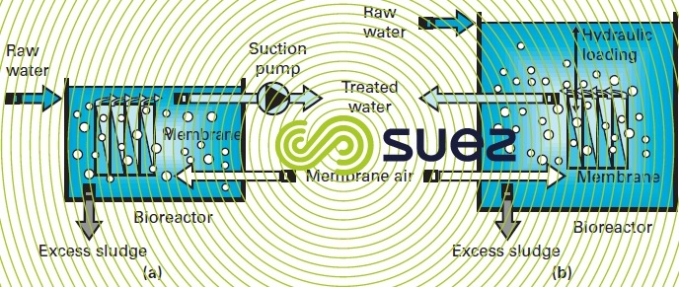
- submerged membrane bioreactors (installed inside the aeration tank – figure 40).
external membrane bioreactors
The membranes are enclosed in a casing. The casings can be mounted in series and/or in parallel. The membranes will be tubular or flat, organic or mineral, called internal skin membranes (filtration takes place from inside the membrane towards the outside).The high suspended solids concentration required for biological purification prohibits the use of dead end filtration. Cross-flow filtration is used – (see Membrane separation). Filtration takes place due to the pressure differential that exists between the inside of the membrane (retentate side) and the outside of the membrane (permeate side).A high cross wash velocity (1 to 4 m · s–1 – 2 to 5 bar pressure) is maintained inside the membrane to control the accumulation of matter on the surface. Chemical cleaning needs to be carried out 2 to 4 times per month.
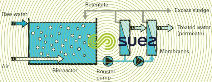

Filtration flows will vary within the 60 to 130 L · h–1 · m–2 range. However, energy consumption (4 to 8 kWh · m–3) associated with crossflow filtration together with the need for thorough pre-treatment in the presence of fibrous materials make this a process that is not very suitable for urban wastewater treatment.
submerged membrane bioreactors
The membranes are placed directly into the activated sludge. The membranes will be hollow or flat, organic, called external skin membranes (filtration takes place from outside the membrane towards the inside).Filtration is carried out by hydrostatic pressure (figure 40-b) or by negative pressure (figure 40-a).Matter that accumulates on the surface of the membranes is controlled using a dedicated aeration system supplemented by automatic cleaning stages (backwash, filtration shutdown – see systems using clarification membranes).
Part of the aeration can be deducted from the biomass’s oxygen requirements. When the membranes are installed in a dedicated tank, there must be recirculation from this tank to the aeration tank. If the membranes are installed directly in the aeration tank, the need for recirculation will depend on configuration (ditch, complete mix, plug-flow).
This process’s modular design allows us to consider refurbishing a plant (extending its capacity or improving its quality) by gradually submerging the membranes into an existing aeration tank.
Filtration flows range from 10 to 40 L · h–1·m–2. Operating pressure is low, in the region of 2 to 5 m of head. Chemical cleaning, requiring that part of the filtration stage to be shut down, must be carried out 2 to 3 times per year.
For its urban and industrial wastewater treatment applications, SUEZ has developed the Ultrafor that uses hollow fiber organic membranes. A more detailed description of this system and its applications and performances can be found in either Ultrafor membrane bioreactor or clarification membrane applications sections.
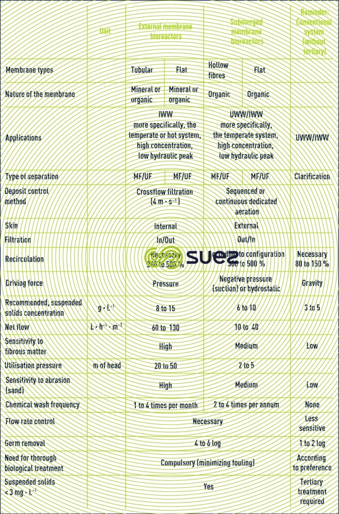
Table 14 summarises the main properties and performances of the different membrane bioreactors, comparing them with activated sludge systems.

Bookmark tool
Click on the bookmark tool, highlight the last read paragraph to continue your reading later
