


Ultrafor membrane bioreactor
Reading time:general presentation
Ultrafor is a biological treatment process forms part of the submerged membrane bioreactor group that has already been discussed in Using clarification membranes in biological wastewater treatment.
It uses ultrafiltration organic membranes, for example GE series 500, hollow fibre type with externally stiffened skin. The biological liquor is filtered by passing water through the membrane from the outside to the inside of the fibre, using the pressure differential created by a suction pump (figure 24).

The fibre has a 1.9 mm external diameter and a 0.8 mm internal diameter. The pore has a nominal 0.04 µm diameter, providing an excellent removal capacity threshold.
The cassette is the smallest functional unit in a filtration system.
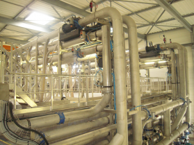
It comprises the following equipment (photo 13):
- the filtration elements (a maximum of 48), each filtration element having a 31.6 m² area;
- filtration and element assembly components;
- the system used to distribute and diffuse air («air membrane» function) along the entire length of the elements;
- part of the system used to attach the cassette to the civil engineering structure within which it will be operating.

operating principle
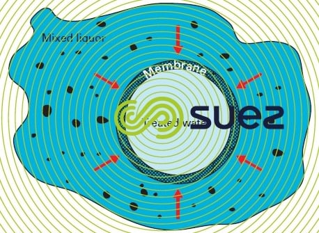
Submerged in the biological liquor, the membrane is responsible for separating the purifying biomass from the purified water. In this way, it replaces traditional clarification and any tertiary filtration.
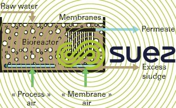
There are two basic Ultrafor configurations (figures 25 and 26):
- one configuration where the membranes are submerged direct in the biological reactor (Ultrafor 1 or integrated). This configuration generally causes a problem in the treatment of nitrogen (impact on denitrification of membrane aeration) and maintenance;
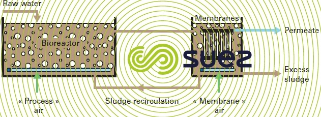
- one configuration where the membranes are installed in a separate filtration tank. In the latter case, the biological liquor has to be recirculated between both tanks (Ultrafor S or separate). This is the most commonly found configuration.
Ultrafor works with filtration/washing cycles.
Filtration takes place by suction or by gravity, under the effect of a trans-membrane pressure that is less than 0.55 bar. Part of the filtered water is extracted for cleaning the membrane. A cyclic aeration («air membrane» function) creates an air flow that rises up the length of the fibres and creates membrane agitation and mixed liquor dynamics in the vicinity of these membranes.
Optimising and implementing aeration systems leads to a good compromise between the effectiveness in terms of continual membrane cleaning and the electricity required to work the blowers resulting in a significant limitation in operating costs.
Additionally, different types of wash, at variable intervals, are also carried out in order to control membrane fouling and trans-membrane pressure changes over time.
- backwash (or backpulse). This wash is carried out by sending permeate back into the fibre against the flow in order to detach impurities attached to its walls. It lasts about 30 seconds at 10 to 15 minute intervals.
- maintenance wash. This wash is carried out as a precautionary measure and consists of a backwash using permeate to which a chemical solution is added. It takes approximately 1 hour and is carried out every 3 to 7 days;
- regeneration wash. This is a remedial wash and consists in soaking the membrane in a chemical solution. It takes less than 24 hours and is undertaken 1 to 3 times a year.
utilisation
Ultrafor, as most membrane bioreactors, is mainly identified by:
- a high biomass concentration, from 8 to 10 g · L–1, providing considerable savings in terms of reactor capacity. Much higher concentrations have been and are still being used at the expense of optimum cost-effectiveness (investment and operation).
- the presence of membranes submerged in the mixed liquor.
Certain precautions or limitations when designing and dimensioning.
pre-treatment
This is a fundamental step in satisfactory filtration unit operation.
Effective straining is compulsory in addition to thorough grit and grease removal. In the absence of any primary settling, the minimum requirement is filtration through a 1.5 mm hydraulic diameter mesh.
biological reactor
With a few exceptions, reactor configuration remains similar to that applicable to the conventional activated sludge process.
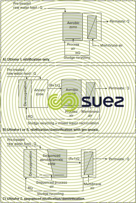
Figure 27 provides three examples of possible configurations.
A higher sludge concentration and the use of membranes do, however, introduce marked differences in terms of dimensioning:
- in order to obtain interstitial water that has a good filtration capacity, the reactor's dimensioning must guarantee comprehensive and stable nitrification (N-NH4 below 1 mg · L–1) under the most adverse loading and temperature conditions. However, in the absence of any standards imposed in respect of total nitrogen, denitrification will be optional because there will be no danger of sludge rising up during clarification, unlike the conventional scheme. Compared with a conventional activated sludge, the reactor capacity required is divided by at least two because of the high sludge concentration:
- the high suspended solids concentration has an adverse effect on the Tp coefficient and, consequently on oxygen transfer. This results in a specific electrical consumption, expressed in kWh·kg–1 of BOD, noticeably higher than that for a conventional activated sludge:
- as filtration takes place inside the cassettes, a super-concentrated mixed liquor is produced. The latter has to be controlled by continuously recirculating the cassettes to the aerobic and/or anoxic tanks. As a rule, the recirculation output is set at 300 to 500% of the supply flow rate.
membrane surface area
Given the effect of peak flow rates on membrane design, it is essential that hydraulic conditions are properly ascertained so that the filtration area can be correctly dimensioned.
When the peak coefficient is high, optimisation solutions such as the buffer capacity or separate treatment of any excess output need to be considered.
The necessary membrane surface area has to be corrected for the influent temperature and the sludge concentration to be filtered through the membranes.
Depending on these parameters, net flows (in L · h–1·m–2) will vary typically between 15 and 35.
performances
Given the physical barrier formed by the membrane, the quality of water processed using Ultrafor is excellent in terms of suspended solids and turbidity, and also of coliform germs. Dimensioning calculated to achieve thorough nitrification also produces low concentrations of COD, BOD and N-NH4.
Table 5 summarises typical performances obtained with this type of plant processing urban wastewater.
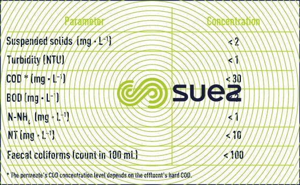
When this level of quality is obtained, it allows consideration to be given to discharging the treated water direct into a sensitive or highly sensitive environment or to re-using it for a number of purposes.
Please refer to main membrane applications for the main applications and advantages inherent to membrane reactors.
Bookmark tool
Click on the bookmark tool, highlight the last read paragraph to continue your reading later
