


clarification
Reading time:clarifier functions
The satisfactory operation of a wastewater treatment plant working with activated sludge needs the treated water to be properly separated from the activated sludge so as to produce a clarified effluent that meets standards on discharge.
Traditionally, this solid-liquid separation can classically be carried out by gravity sedimentation in a secondary settling tank or clarifier, even when other processes, such as flotation, can also apply (albeit at greater cost).
The clarifier is a fundamental part of the activated sludge system. It has to combine three functions:
- clarification: producing a final clarified effluent with a suspended solids content that is generally below 20-30 mg·L–1, i.e. separation efficiency better than 98%;
- thickening function: producing a continuous output of concentrated sludge for recirculation in the biological reactor, ensuring the latter’s suspended solids settings are maintained et extraire les boues en excèsand the excess sludge extracted;
- storage: storing the additional mass of sludge produced as the result of a transient hydraulic overload (particularly during rainfall episodes).
Should any of these three functions fail, suspended solids will be discharged with the outgoing water, with two consequences: deteriorating quality of water processed with regard to suspended solids and also to COD, BOD, TN and TP and the danger of deteriorating biological operation through the uncontrolled reduction in biomass concentration.
The clarifier’s behaviour in each of these three functions will be influenced by various factors, the main ones being the most important in terms of design are the throughputs of water to be treated and sludge properties (settling and thickening capabilities). Other factors such as the structure’s physical and hydraulic characteristics, the design of the degassing area between the biological reactor and the clarifier, especially in the case of very deep reactors (over 7 m deep) will also apply, particularly in terms of achieving very low suspended solids concentrations.
clarifier dimensioning
Secondary settling dimensioning requires the determination of three parameters: tank surface area, sidewater depth and sludge recirculation rate.
The following calculation rules have been derived from ATV dimensioning recommendations. These rules apply to circular and rectangular clarifiers.
the tank surface area
This surface area is established on the basis of permissible surface loading (in m3·m–2·h–1), more generally known as the rising velocity Va defined by the following formula:


where:
- Cba (in g · L–1): suspended solids concentration introduced into the clarifier:
- DSVI (diluted sludge volume index) (mL · g–1): the sludge index (volume of sludge VD30 occupied by one gram of suspended solids after thirty minutes settling time in a one litre test tube after dilution if necessary in order to ensure that VD30 ranges from 100 to 300 mL).
The minimum clarification surface area required Smin is such that:
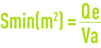
where Qe (m3·h–1): maximum permissible flow rate, equal to the peak flow rate during dry weather or to the peak flow rate during rainfall according to the case.
From this approach, it ensues that the surface area of a structure will increase with the sludge volume index and/or the sludge concentration in the aeration tank. Since, conversely, biological reactor capacity decreases as sludge concentration rises, it is worthwhile producing economic optimisation calculations for the biological reactor-clarifier pair by altering concentration Cba.
These dimensioning criteria have been established with a view to achieving, in principle, a discharge suspended solids content that is below 20 mg · L–1 with thoroughly flocculated sludge. However, it should be noted that this suspended solids content is not exclusively linked to rising velocity and the DSVI but also to the clarifier’s construction features and to floc structure.
As it is not an easy matter to forecast sludge flocculation properties (this depends on the ecological conditions imposed on bacteria), it is difficult to accurately establish, within the 5 to 30 mg · L–1 range, actual suspended solid concentration in clarified water.
sidewater depth
This depth is also an issue that is fundamental to satisfactory clarifier operation. Depth is defined using empirical rules, based on the principle that the depth of a structure can be broken down into four super-imposed zones each carrying out different functions (figure 10).
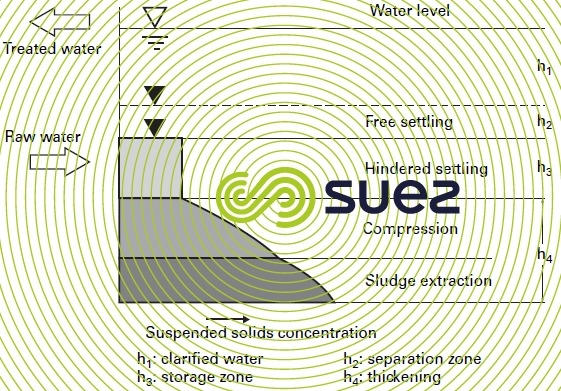

h1: clarified water zone.
h2: separation or free sedimentation zone.
h3: sludge storage zone (safety precaution during rainfall episodes), linked to the flow of deconcentrated matter from the aeration tank.
h4: sludge thickening and discharge zone.
The sum of the four figures hm = h1 + h2 + h3 + h4 represents the structure’s average depth. For a circular structure with a sloping floor, this depth will be measured at one third of the radius in from the periphery.
In practice, h1 is regarded as equal to 0.50 m. Depths h2, h3 and h4 are calculated for the plant’s peak throughput and the associated recirculation flow rate. These figures also depend on sludge concentration Cba and on the sludge index DSVI. Additionally, h4 allows for maximum sludge contact time in the thickening tank of tth; tth varies between 1 hour and 2.5 hours depending on the biological system’s operating criteria.
Total depth hm must never fall below 3 m for structures having a diameter equal to or greater than 20 m. Beyond 20 m, hm must not fall below 2.50 m
Recirculation rate
Maximum sludge concentration on the clarifier floor (Cbr max) is established by the following formula:

Cbr is used to calculate the minimum sludge recirculation rate according to the different hydraulic operating conditions, using the Rmin = Cba/(Cbrmax – Cba) formula. We recommend using a safety margin in addition to the value obtained in order to allow for the dilution effect created by the sludge collection system (scraped or suction).
Given that a plant’s incoming flow rate will fluctuate significantly during the course of a day between peak and minimum flow rate, ideally, it should be possible to adjust the recirculated flow rate within a certain range. This operational flexibility must be taken into account when selecting pumping equipment.
solids loading
The concept of solids loading also needs to be considered for clarifier design. The solids loading is the total quantity of suspended solids fed into the clarifier (including recirculated sludge), in relation to the settling surface area and expressed in kg suspended solids · m–2 · h–1.
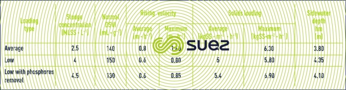
applications
Table 3 summarises typical clarifier operating conditions together with the recommended structure depth for the various activated sludge applications.
technological considerations
equilibrium stack
The mixed liquor coming from the aeration tank arrives in the centre of the clarifier through a underground pipe. The central tank feeds the centre of the clarifier. There is separation housing (also called Clifford inlet) around the centre which enables the flow entering the chamber to be uniformly separated without disrupting the settling process.
bottom sludge collection
The units responsible for this operation must allow for a controlled return of thickened sludge to the biological reactor and restrict the time taken by the sludge to travel through the settling tank (tth maximum). Various solutions can be considered with a view to limiting this time:
- restricting the size of scraped clarifiers to a maximum of 30-35 m depending on the case (temperature, F/M ratio …);
- increasing the floor slope, enabling the scrapers to draw sludge in from the periphery to the collection pit faster or, even better, using sludge suction tubes which, in theory, allows the sludge to be collected at each scraper pass, regardless of clarifier size (see Flocculators – settling tanks – flotation units).
collection treated water
Generally, clarified water is removed through the overflow system using a notched weir sometimes preceded by a syphon-shaped partition which holds back the floating material. The uptake must be designed so as to avoid sludge being sucked up towards the outlet ducts. This implies that sludge beds are well managed and kept under the level of the settling zone and that overflow speed does not exceed 15 to 20m3/meter/hour. Water uptake may also be carried out by submerged pipes.
Bookmark tool
Click on the bookmark tool, highlight the last read paragraph to continue your reading later
