


sequencing batch reactor process
Reading time:general
The sequencing batch reactor process ( SBR ) involves a single complete mix type reactor in which aeration takes place followed by clarification, whence the designation “sequential”. Sludge settles when aeration is shut down and a drainage mechanism used to draw off the supernatant liquor. The various treatment stages take place at predetermined and programmable intervals, all the stage constituting a cycle.
A typical cycle comprises five sequences grouped to form three phases (figure 19):
- feed (raw or clarified water) and reaction (aeration/mixing in the tank);
- settle (separating out the suspended solids);
- decant (drawing off the treated water) and then idle (extracting excess sludge).
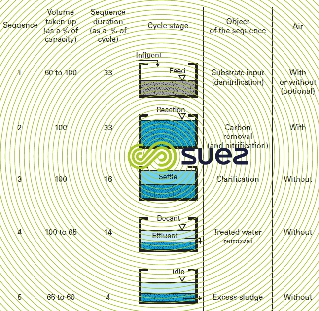

The final idle stage can be eliminated by removing the sludge at the end of the drainage period. The durations quoted are provided for information as a percentage of the total cycle that can fluctuate between 4 and 12 hours, or even more for some IWW. These durations may vary according to the influent concentration and because the aim is the exclusive elimination of carbon or the elimination of carbon and nitrogen, or even phosphorous.
In this type of system, with one single tank, effluent feed and discharge will be intermittent. In order to achieve continuous infeed, a second tank has to be added, offset by half a cycle in the case of the example selected. However, at least four tanks will be required in order to ensure a constant outflow.
All the concepts specific to activated sludge (BOD loading, F/M ratio, sludge age) apply in the same manner to SBR, even though biological and hydraulic behaviour is slightly different.
Based on this fundamental principle, a number of variants to this process have been developed, all using intermittent decant. Previously used by small and medium capacity plants, the SBR technique now applies to major urban areas (over 1 million p.e.).
We give below the advantages and drawbacks associated with this type of system.
on the plus side:
- elimination of the secondary settling tank and of sludge recirculation (in principle);
- these systems tolerate flow rate and pollution loading variations;
- very good clarification conditions; in particular, excellent control of sludge anoxic and even anaerobic timing during clarification, resulting in excellent sludge indices and low suspended solids contents;
- simple and compact construction, creating noticeable savings in terms of civil engineering works.
on the minus side:
- air system has to be over-designed because of the reduced aeration time per cell;
- an elaborate and high performance decant system is essential;
- danger of floating matter, giving rise to the need for an appropriate evacuation mechanism.
For some time, SUEZ has been developing sequential systems, starting for fixed water levels and appropriate to small plants: the Diapac UI and then the Alter 3 (during the 70's and 80's). Finally, having recognised the advantages of batched systems (during the 90's), two systems, including the Cyclazur were offered, leading to the following two systems at present:
- for small size plants, the Bio S (see compact units bio-S process);
- for medium to large size units, the Cyclor described below.
cyclor
The Cyclor has a minimum of two cells in order to provide a continuous supply. Each cylindrical or rectangular reactor is of the variable water level type
principales phases du cycle
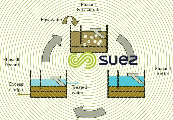
The successive phases that take place in the same cell follow the sequence detailed below (figure 20):
- cell fills and reaction (phase 1): the influent arrives into a selector (plug-flow zone at the cell inlet) where it comes into contact with part of the recirculated sludge. The liquid level rises in the cell and aeration commences. The various biological reactions take place during this phase: carbon treatment and nitrification during aeration, denitrification when aeration is shut down if applicable (rhythm and rate can still be set);
- sedimentation (phase 2): sludge recirculation and aeration is shut down. It is during this period that sludge static sedimentation takes place together with endogenous denitrification within the biological floc;
- drainage (phase 3): after sedimentation, clarified water is removed using an appropriate mobile mechanism. Sludge blanket sedimentation and endogenous denitrification continue. Excess sludge is extracted at the end of the drainage period.
main components of the Cyclor (figure 21)
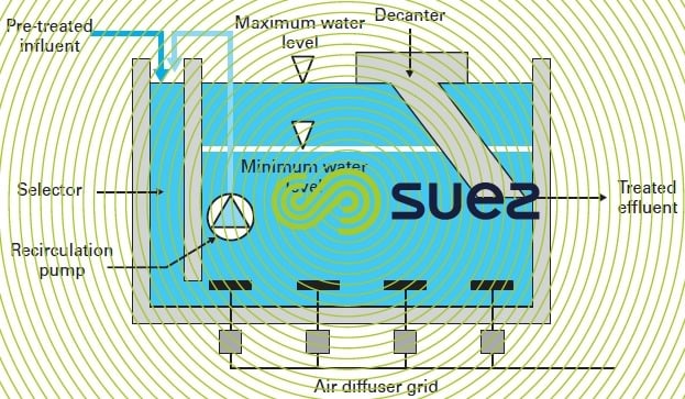
the selector
The pre-treated influent generally arrives into the selector (plug-flow zone) where it is placed in contact with a part of the sludge recirculated from the tank to the selector via a submerged pump.
This selector acts as a contact zone and, depending on its characteristics (plug flow, hydraulic contact time), will:
- reduce the risk of bulking by preventing the development of filament type bacteria and by improving sludge settleability;
- encourage biological phosphorus removal and denitrification reactions.
the air diffuser grid
Air is injected into the tank through fine or medium bubble diffusers set in the tank floor. This mechanism is controlled by a measurement of the dissolved oxygen found in the Cyclor cell using programmed dissolved oxygen concentration settings. Using the GreenBassTM regulation system is also suitable.
The standard Cyclor is not fitted with an agitator. The injected process air ensures that the tank contents are mixed and that sludge suspension is reinstated during any anoxic phase by short bursts of air spaced out in time. Consideration can be given to the inclusion of a submerged agitator.
the treated water collection system
This equipment, responsible for removing the water layer, is essential to Cyclor satisfactory operation. It must ensure that the effluent is removed within the time allocated to the drainage phase while avoiding different floating matter being drawn off and do so without drawing up the sludge blanket located below the clarified water phase.
Cyclor reactors are equipped with a treated water collection system that uses a floating weir based on patented technology.
This mechanism tracks the water level from the maximum level that exists when drainage starts down to the minimum levels that occur at the end of the drainage stage. This minimum level is set in such a way as to be sufficiently distant from the upper section of the sludge blanket in order to avoid any sludge being drawn away with the treated water.
The decanter comprises (photo 12 and figure 22):
- a floating mechanism;
- a weir with a scum baffle positioned above the floater;
- a rigid, hinged pipe used to remove treated water (gravity flow).

With the exception of the drainage phase, an automatic locking system, i.e. using injected air, ensures that the system remains sealed. The air blanket thus formed below the floater seals the system against any sludge penetration. At the commencement of the drainage phase, an electrically operated solenoid valve opens the weir, allowing the air blanket to leak out and the treated water to flow away.
During the drainage stage, the floating weir drops down with the water level. When drainage is complete, the pneumatic lock is re-activated before the system is refilled.
This collection system is particularly appropriate to the process: no floating matter is drawn away (scum baffle positioned 10 cm below the water level), no electro-mechanical unit required to activate weir travel nor to lock it.
The output removed by the weir varies with the water depth: high to start with, low at the end as the water level comes down to the sludge blanket. It depends on the water depth at the start and end of the drainage phase, on the discharge level and on downstream hydraulic limitations.
There are four sizes of decanters available for removing unit flows ranging from 250 m3 · h–1 to 1 200 m3 · h–1. Clearly, several units can be used in conjunction with one single cell.
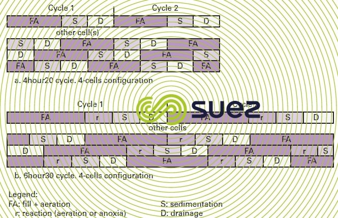
cycle configuration and duration
The shape of the reactors and the number of Cyclor cells are selected according to land limitations and to the size of the plant.
Cycle durations are programmed but can be adjusted to suit influent characteristics. Three types of standard cycles can be used: short, long and very long. They differ by the time allotted to the reaction phase, sedimentation and drainage times being identical. This system allows us to process water that is more or less concentrated, to achieve the most stringent discharge guarantees, especially for total nitrogen, and to adjust to adverse temperature conditions (nitrification during winter months).
Moreover, Cyclor will produce good biological phosphorus removal performances.
Figure 23 illustrates two examples of cycle configuration.
avantages et drawbacks
Compared with conventional activated sludge, the Cyclor has the following main advantages:
- optimum sludge sedimentation: static sedimentation without causing any hydraulic disturbance, a very good sludge index (role played by the selector and short periods without any aeration);
- simple civil engineering concept with significantly reduced ground area covered because there are no separate clarifiers. Therefore, Cyclor is a relevant response to land and environmental (need to cover over structures) restrictions … thus positioning itself between classic activated sludge and biofilters;
- modular design and operation;
- controlled entirely automatically with the possibility of easy timer adjustment.
The drawbacks, as in the case of all SBR units:
- the air system has to be over-designed because of its cyclical operation (limited aeration time);
- tank capacity has to be over-designed when a high hydraulic peak coefficient applies (over 3);
- in some cases, downstream storage will be required when tertiary treatment is included.
Bookmark tool
Click on the bookmark tool, highlight the last read paragraph to continue your reading later
