


activated sludge reactor: type and configurations
Reading time:Bioreactor general characteristics were described in substrate properties. The content "reactor types" details the types of reactor specifically used with activated sludge, together with the influence of the reactor’s hydraulic organisation on purifying performances, irrespective of sludge age and loading criteria. Please refer to "Main activated sludge configurayions" for the main activated sludge treatment processes currently used by SUEZ.
reactor types
complete-mix
By definition, this reactor is a totally homogenous tank where micro-organism, oxygen and residual substrate concentrations (figure 11) are identical at all points in the tank.
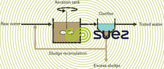

The influent is immediately dispersed throughout the reactor and the interstitial liquid represents the treated effluent. The advantage of a complete mix is that, within certain limits, it tolerates pollution overloads and any short periods of toxic shocks.
However, the low level of substrate available in the micro-organism environment can encourage the growth of filament-like bacteria and cause bulking problems («low F/M bulking»).
plug flow
The influent and recirculated sludge come into the tank inlet that is arranged to form a very long channel (figure 12).
Substrate concentrations and the activated sludge liquor’s oxygen demand will vary along the entire length of the channel. That is why the installed oxygenation capacity normally declines from upstream to downstream (tapered aeration). This type of tank is particularly suited to large plants.
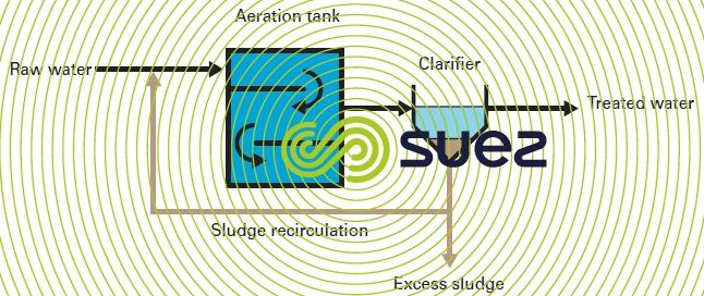
The fact that the tank inlet is operating under high load limits the growth of most of the filamentous bacteria and enhances the sludge’s settle ability, providing that sufficient dissolved oxygen is maintained.
step feed
This is a variant of the plug flow reactor where the influent is injected at various points into the aeration tank, consisting of a series of parallel cells. All the recirculated sludge is injected into the tank inlet (figure 13).
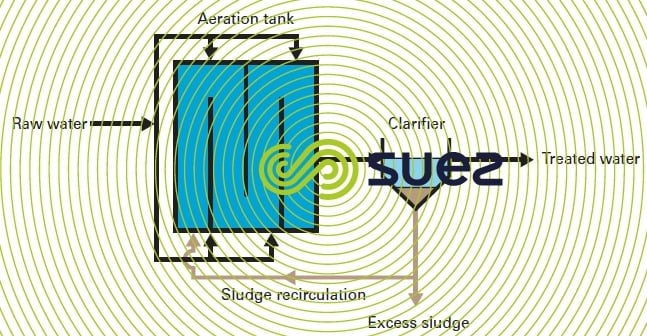
Thus the F/M ratio and oxygen demand are far better distributed than in a plug flow tank. Sludge concentration drops from the tank inlet to its outlet so that, given the same suspended solids concentration at the clarifier intake, there is a markedly higher sludge mass in the reactor.
dicth (or closed loop tank)
Originally, this reactor had been designed as an oblong ditch with a central partition equipped with horizontal shaft aerators in a punctual arrangement (oxidation ditch) (figure 14).
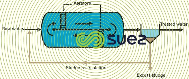
Nowadays, it is also constructed in the shape of a ring, with pressurized air aeration and mechanical agitation resulting in a minimum 0.30 m · s–1 circulation velocity. Thus, this reactor comes close to the complete mix reactor.
Design for a tank operating under high loads:
In the case of tanks operating with high loads where only carbon pollution is removed, oxygen demand is high in the first half of the unit but much lower in the 2nd half. Under these conditions, injecting air to meet oxygen requirements only, does not allow mixing in the 2nd part of the unit to occur.
To resolve this problem and to limit energy consumption, a "high-load" type tank has been designed made up of a piston flow zone comprising a series of several integral-mix tanks (high oxygen demand and mixing by injecting air) followed by a ditch-type tank in which mechanical agitation occurs.
This design allows oxygen supply to be optimised whilst ensuring optimal mixing throughout the entire tank and correct biological conditions which guarantee correct functioning.
special case : the selector
The contact zone is an integral mixing-type agitated tank receiving feed water and recycling water .
The contact zone or the selector, are used in combination with some of the reactors discussed earlier. This process principle comes from the Chudoba works (1973) aimed at controlling filament bulking and at enhancing the sludge’s sedimentation capacity.
The principle consists in creating an area with a high concentration of soluble assimilable substrate that stimulates the substrate’s uptake rates and storage capacity for non-filament type germs. The latter then have a growth rate that outstrips that of filamentous type micro-organisms, allowing the flocculating germs to dominate.
In practice, this requires the use of a small capacity tank immediately upstream from the aeration tank where the recirculated sludge and wastewater are mixed.
Dimensioning is based on two parameters: contact time at peak output (approximately 10 to 30 minutes regarding the conception) and a rapidly assimilated COD loading applied to the zone (approximately 100 mg COD · g–1 suspended solids).
Different types of selectors (or contact zone) are used, operating in aerobic, or anoxic conditions, with various levels of effectiveness depending on the operating conditions encountered.
main activated sludge configurations
Typical tank configurations used to eliminate BOD do not call for any specific comment: complete mix or plug flow reactors (and their variants), average, heavy or even heavy loading depending on the target purification performance, and continuous aeration.
Consequently, this paragraph will only discuss some of the configurations used by SUEZ for removing nitrogen (nitrification and denitrification) or for combined nitrogen and phosphorous removal.
process with an upfront anoxic zone (Modified Ludzack-Ettlinger , also known as MLE) figure 15
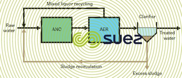
In this very popular configuration, the influent enters an anoxic zone and then, an aerated zone. The nitrates formed are recycled to the anoxic zone through sludge recirculation on the one hand and through mixed liquor internal recirculation on the other. The internal recirculation rate can vary from 100 to 350% of the raw water flow rate depending on the target denitrification performance.
Denitrification effectiveness depends on the recycling rate; the anoxic contact time and, above all, on the readily biodegradable fractions of the BOD contained in the raw water. An influent BOD/NK ratio of 4: 1 will be enough to obtain a 5 to 7 mg · L–1 outgoing concentration of nitrates and to satisfy the discharge standard of 10 mg · L–1 with regard to NT from dilute raw water(40 mg · L–1NK maximum).
For a higher NK concentration and/or a lower BOD/NK ratio compared with these values, this process will be limited by the denitrification performance which governs the achievable NT level.
three-zone process (figure 16)
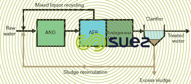
The previous configuration is supplemented by a so-called endogenous zone located downstream from the aerated zone. This zone is equipped with aeration that operates intermittently and with a separate mixing device. Mixed liquor is recirculated to the pre-anoxic zone from the aerated zone outlet.
Anoxic zone design is calculated for the denitrification, as a maximum, of the flow of nitrates made possible by the quantity of readily biodegradable BOD (inclusive of dissolved oxygen). The additional denitrification required is carried out by endogenous respiration in the zone of the same name.
Due to its design, the three-zone process has a number of advantages:
- it is a highly efficient denitrification system, thus resulting in low total nitrogen concentrations;
- high NK concentration and/or low BOD/NK ratio raw water can be processed;
- reduced internal recirculation rates because nitrates are recycled at a concentration that is markedly higher than that of treated water.
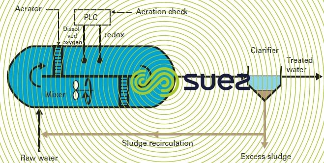
nitrification-denitrification ditch (figure 17)
In this application, the ditch operates alternately under aerobic and anoxic conditions, sequencing the aeration and using submerged agitators to maintain a minimum circulation velocity in the tank.
Air supply can be managed by regulating GreenbassTM sequenced aeration. The GreenbassTM principle is based on measuring the concentration levels of ammonia nitrogen and nitrate nitrogen.
Following a period of anoxia, aeration is activated when the nitrates formed during the previous aeration phase have been totally consumed by the denitrification process. Aeration is halted when the accumulated ammonium has been oxidized.
The number and duration of aeration-non aeration cycles varies throughout the day, particularly according to the incoming nitrogen loading. In general, the aeration duration will fluctuate between 12 and 18 hours per day with an average of 14 hours.
The advantage of this process is its ability to adapt to water having variable properties. Properly dimensioned, this process will enable nitrate concentrations of approximately 4 to 7 mg · L–1 to be achieved. The inclusion of a contact zone upstream from the reactor is recommended with a view to limiting the danger of filament type organisms developing (complete mix type reactor).
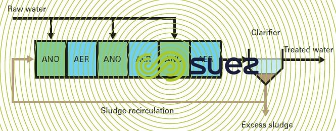
multiple stage process (figure 18)
When implemented to remove nitrogen, this process comprises several anoxic-aerobic reactor assemblies (two, three and even four) in series. It works on the stepped feed principle described in the preceding paragraph with the influent being distributed at the anoxic zones in order to supply the organic carbon required for denitrification.
The system’s design can be symmetrical, i.e. with anoxic-aerobic assemblies of identical capacity and an even distribution, or it can be non-symmetrical in order to make the best of the higher suspended solids concentration at the reactor inlet. With this configuration, it is possible to reduce or even eliminate mixed liquor internal recirculation because the nitrates produced in one stage are reduced in the following stage, excluding the final stage.
Given its complex construction, this process tends to be reserved for the high capacity plants.
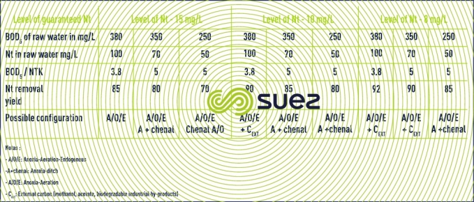
selecting the process
Given the diversity and proliferation of activated sludge processes available on the market, it is not always easy to select the most appropriate process. Among other parameters, the choice is linked to raw water properties, to the prevailing standards on discharge and to the size of the plant.
As an illustration, table 4 recaps the criteria that can be used as a guide to selecting nitrogen removal processes.
Bookmark tool
Click on the bookmark tool, highlight the last read paragraph to continue your reading later
