


biological filters
Reading time:general
The term biological filters or biofilters used in wastewater treatment includes all the processes that combine biological purification through attached growth with the retention of suspended solids.
This technique applies thin biological films that are regularly renewed by washing (12 to 48 hours cycles). This provides a biomass with a concentration and, especially, an activity that are higher than for activated sludge. Compared with activated sludge, this technique has the following main advantages:
- space saving, by eliminating the clarification stage. By virtue of the system’s compact nature, its structures can more easily be covered over, controlling olfactory and noise nuisances and producing aesthetically acceptable plants;
- no danger of leaching because the biomass is attached to a support that is used to adapt to flow rate variations;
- appropriate for use with diluted wastewater, as water velocities can be very high (see below) without adversely affecting treatment;
- modular construction and easy to automate (comparable to drinking water plant filter batteries).
Oxygenation can be carried out by dissolving the oxygen in the air beforehand (see Flopac), or by injecting air direct into the reactor (see Biofor).
flopac
Theprocess whereby oxygen is pre-dissolved in the water to be treated has been implemented in tertiary filtration for applications where, in addition to a thorough removal of suspended solids, a reduction in residual BOD and nitrogen was also sought. The Flopac process developed by Degrémont during the 70’s, meets the requirements of this application. This process’s limitations are set by the maximum amount of oxygen that can be dissolved. At atmospheric pressure, it is in fact difficult to achieve better than 85% of saturation, or 6 to 9 mg · L–1 of O2 depending on temperature. This figure can be doubled by recycling 100% of the treated water output but, at best, this would allow us to eliminate 15 to 20 mg · L–1 of BOD or a few mg/L of nitrogen.
In the case of limited surface filters it is possible to operate these under pressure.
Flopac is now designed as a tertiary filter, operating in downward flow and with either 1.36mm sand or 1.7mm Biolite as the supporting media. The filtration velocity varies from 5 to 15m/h depending upon the case in question and is used as a polishing treatment following advanced secondary treatment (activated or fixed culture sludge) even following tertiary treatment.
During the start of the 80’s, this air supply limitation resulted in the development of reactors where oxygen was transferred inside the reactor. In this case, the respective air and water flow directions are exceedingly important. The practice involving drinking water filtration led to an initial approach where reactors were designed with downward flows running against the air flow. This technique raises a number of problems:
- surface fouling by suspended solids. The rising air flow impedes the filtration front and in-depth fouling. This generates a rapid rise in head loss with a reduced treated output and shorter cycles.
- air binding. The water and air backflow causes the air bubbles to coalesce. Air pockets will form within the material, resulting in «air binding».
- creating unpleasant odours. The raw effluent will be found in the top of the filter where gas bubbling causes unpleasant smelling products to be evaporated.
These different problems have adverse repercussions on downflow water current biofiltration and, after 1982, caused Degrémont to adopt the rising air and water co-current system (Biofor process). With one notable exception: in drinking water nitrification, the air and water counter-current technique can still be used because the low air flows reduce the danger of air binding (Nitrazur process, see Biological engineering applications in potable water treatment).
the Biofor
main characteristics
The Biofor is a biological reactor where bacteria are attached to a specific single layer material that is fixed and submerged. This material called biolite is based on expanded clay having a density greater than 1.2 and provides a high degree of roughness and an extensive specific surface area. This property is used to maintain a bacteria film that is sufficient for very quickly restarting the biological process, even after a vigorous hydro-pneumatic wash.
The Biofor works with a rising water and air flow, thus offering a number of advantages: hydraulic loading can be high, high suspended solids retention capacity (good suspended solids spread throughout the filter depth), high oxygenation efficiency.
Oxygenation is carried out by diffusing air, called process air into the base of the filter medium. A series of interlinked manifolds ensures an even distribution. Membrane diffusers called Oxazur are mounted on these manifolds.
Regular washes are used to eliminate any sludge that has accumulated in the material through bacterial proliferation and the retention of suspended solids. These air and water backwashes are automatically controlled and initiated either by a maximum head loss or by a preset maximum cycle duration. Dirty wash water is collected in a tank before being treated and recycled.
Developed at the start of the 80’s for use in urban wastewater secondary purification, different variants of the Biofor gradually became available for use in a range of functions. Biofor units can be divided into two groups:
- the aerated Biofor: Biofor C used in carbon removal, Biofor CN in carbon removal with partial nitrification, Biofor N for advanced nitrification;
- the non-aerated Biofor: Biofor pre-DN or post-DN for denitrification.
aerated Biofor
description
A Biofor system comprises a battery of identical reactors that usually consists of a rectangular concrete casing, each enclosing (figure 30):
- a well supplying water to be treated and equipped with a protective strainer;
- a granular matter support floor with a fluids injection and distribution system;
- two front-mounted weirs for collecting treated water and wash water. These weirs are protected by a stilling fence that eliminates turbulence and releases air bubbles that may then attach themselves on to the biolite grains;
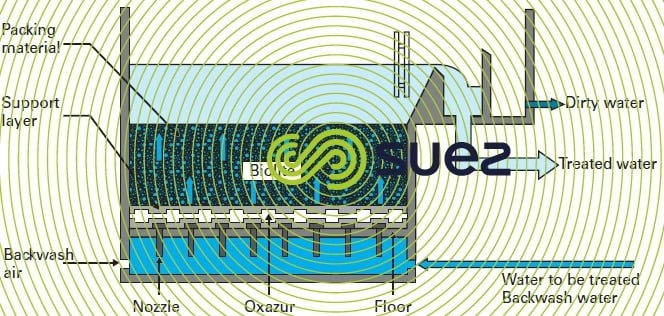

- a front-mounted collection chute specific to each filter and a part of the collection channel shared by the filter battery.
Two intermediate support layers and approximately 3 to 4 m of biolite material are laid over the floor. Fluids injected beneath the filter floor (raw water, wash water, wash air) are evenly distributed by nozzles (installed at the rate of approximately 50 per m²) of the same type as those found in sand filters but that have been specially adapted for wastewater.
Process air is injected and evenly distributed throughout the support layer by deformable elastic membrane diffusers, installed at the rate of 25 or 50 units per m² of floor area.
The density and granulometry of the biolite material is selected according to its intended utilisation. Two types of material are routinely used in aerated Biofors:
- biolite L 2.7 (crushed) or P 2,7 (round), having an effective size of between 2.5 and 2.9 mm;
- biolite P 3.5 having an effective size of between 3.2 and 3.8 mm.
Other granulometries can be used for individual applications.
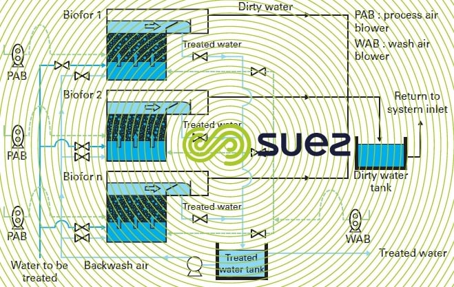
In addition to this bank of reactors operating in parallel or, if necessary, in parallel series, the Biofor system also comprises (figure 31):
- a structure for distributing water to be treated;
- a gallery providing access to the automatic valves and to the pipeline systems, to the filter floors, drainage …;
- adjacent premises housing the wash pumps;
- premises housing the various blowers and air compressors;
- a treated water tank for the wash water;
- a wash water storage tank with extraction pump.
operation-Automated controls
The screened raw water is introduced into the system below the reactor floor. The number of filters in service will depend either on the throughput to be treated or on the pollution loading applied to the battery.
Process air is continuously introduced into the filters in service. It is supplied either by a blower specific to each reactor or, especially in the case of major plants, by an air generator and a modulating valve at the entrance to each of the biofilters.
The treated water is collected by a front-mounted weir and is removed by gravity to the final discharge after the wash water storage tank has been filled. Alternately, the treated water is routed to a second biological stage.
The entire backwash cycle is automatic and lasts approximately 50 minutes. It comprises several sequences, broken down into an air and water backwash phase and a rinse phase followed by a final rinse phase. The amount of treated water consumed per wash is approximately 10 m3·m–2 of filter, wash water normally accounting for 5 to 8% of the volume of water filtered by each treatment stage.
A programmable logic controller (see instrumentation and measurements «Biofor» architecture) controls wash cycle management, rotating machine and automatic valve operation.
applications and performances
The Biofor is normally put into operation after primary settling, physical-chemical treatment or biological treatment to treat residual urban or industrial water.
The following constitute its preferential areas of utilisation:
- applications where site limitations or ground quality render its compact nature advantageous (this system covers 3 to 5 times less ground surface area than activated sludge variants);
- plants experiencing sudden hydraulic overloads (e.g.: discharge during rainfall periods). Because the biomass is fixed, it cannot be lixiviated and performances, including nitrification efficiency, will be reinstated no later than after the first wash.
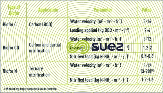
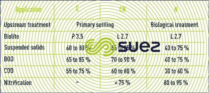
Tables 6 and 7 show permissible velocities and loadings for the various types of aerated Biofor, together with customary average performance levels. These values are subject to change depending on certain conditions: temperature, biodegradability and typology of the water to be treated, especially with regard to soluble/particular ratios.
removal BOD
With medium concentration primary settled urban wastewater, BOD loadings of 2 to 4 kg DBO · m–3·d–1 will reliably produce a BOD of less than 25 mg · L–1. This figure can even exceed 6 kg DBO · m–3 · d–1 with diluted water (BOD below 70 mg · L–1).
These applied loadings will vary depending on temperature. On the other hand, the granulometry of the material used has little effect on BOD removal.
nitrification
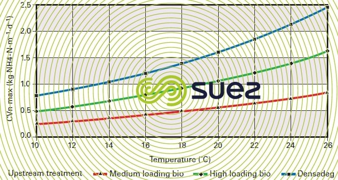
Maximum nitrification capacity CVn max. (in kg N-NH4·m–3·d–1) is significantly affected by temperature, like any nitrification process, and also by the readily assimilated carbon/ N-NH4+ ratio and, therefore, by upstream treatment. This fact is illustrated by table 7 and figure 32. Table 7 shows that a 1.5 kg·m–3·d–1BOD loading reduces eliminated nitrifying load by a factor of approximately 3. Similarly, the curves in figure 32 clearly indicate the impact made by dissolved BOD on nitrification (declining physical-chemical treatment for average loading treatment).
When partial nitrification is required (less than 70% NK efficiency), only one bio-filtration stage will be needed. This is the Biofor CN. We recommend removing a maximum of carbon upstream using a primary physical-chemical treatment.
When advanced nitrification is required (80 to 96% NK efficiency), advantage can be gained from removing as much carbon as possible over a first stage. Ideally, the Biofor N should be preceded by a Biofor C stage or by a medium loading activated sludge treatment stage. Approximately 1.6 kg N-NH4·m–3·d–1 can then be nitrified at a temperature of 20°C.
For intermediate nitrification efficiencies (65 to 85%), we recommend comparing a single stage solution (Biofor CN) with a two-stage solution (Biofor C followed by the Biofor N) before reaching a decision.
removal suspended solids
Biofor performance depends on the choice of material, on the suspended solids concentration in the influent and on hydraulic loading in the filtration stage. For water to be treated that has an initial suspended solids content of less than 100 mg · L–1, suspended solids removal efficiency will vary from 75 to 85% at water velocities of 3 to 6 m · h–1.
excess sludge production
Suspended solids retention and of an increased heterotrophic and autotrophic biomass create excess sludge production. Excess sludge production is characteristic of medium loading biological systems, allowing for enhanced suspended solids collection. Between two washes, retention capacity normally ranges from 2 to 4 kg suspended solids · m–3 of matter.
These suspended solids are collected in the form of wash water having an average concentration of between 200 to 800 mg · L–1 depending on the application. These suspended solids are either returned to a point upstream from primary treatment or processed separately by sedimentation or floatation. It should be noted that the sedimentation and dewatering capacity of this sludge is far better than that of activated sludge.
process air velocity
The process air velocity (Nm3·m–2·h–1) must meet the following oxygen demands: carbon oxidation, nitrogen N-NH4 oxidation and endogenous respiration. Depending on application conditions, process air velocity can vary from 5 to 25 Nm3 · m–2 · h–1, or more in tertiary nitrification carried out at high temperature levels. The oxygen transfer efficiency, under effective conditions, ranging from 15 to 25%, the oxygenation energy take-up will be between 0.5 to 0.7 kWh per kg of BOD removed (at full load) or between 2.5 and 3.1 kWh per kg of N-NH4 nitrified. To this expenditure, we need to add the energy consumed by the periodic packing backwashes; this energy consumption is approximately 0.1 kWh per kg of BOD removed by a Biofor C and 0.15 kWh per kg of N-NH4 nitrified in a Biofor N.
non-aerated Biofor (denitrification)
description
The non-aerated Biofor or Biofor DN is used to reduce nitrates biochemically into molecular nitrogen by means of denitrifying bacteria attached to the material.
The Biofor DN design is similar to that of the aerated Biofor. However, the Biofor DN differs from the aerated Biofor in the following respects:
- no process air supply system;
- material granulometry; the Biofor DN mainly used biolite P 4.5 having an effective size of 4.2 to 5 mm, without any support layer. Biolite P 3.5 can also be used for certain applications. The effective size of the supporting media used in denitrifcaiton is always higher than that used in other applications. This can be explained by the stickiness of the denitrification sludge and the need for aggressive scrubbing.
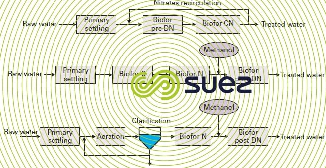
Depending on its position in the treatment system, there are two types of Biofor DN (figure 33), used in combination with other Biofor units or with an activated sludge: the Biofor pre-DN and the Biofor post-DN. The assimilable organic carbon required for denitrification purposes is supplied either by the readily biodegradable BOD in primary clarified water in the first case, or by an external source of carbon, usually methanol, in the second.
applications and performances
The application and dimensioning criteria applicable to both types of Biofor DN are markedly different (table 8):
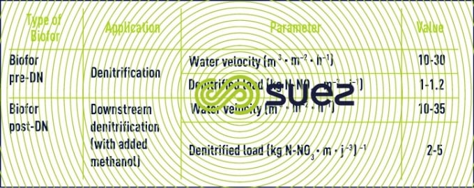
NB: The performance of denitrification and the final concentration level in nitrates will influence the load removed.
- Biofor pre-DN :
The Biofor pre-DN is included in the system after primary clarification, with or without the addition of chemical reagents, and in combination with a Biofor N positioned downstream. The nitrates formed by nitrogen ammonia oxidation in the Biofor N are partially recycled upstream from the Biofor pre-DN and denitrified using the organic carbon contained in the settled water.
Consequently, denitrification efficiency is directly related to:
- the rapidly biodegradable fraction of COD contained in the influent, in other words, the soluble COD/recycled N-NO3 ratio. It should be noted that a proportion of the colloidal fraction of the COD is also mobilized at he nitrate recirculation rate, that can vary between 100 and 200% of the incoming flow.
With typical urban wastewater having a COD/NK ratio of approximately 10 to 13, this configuration will be quite appropriate when a 50 70% total nitrogen removal efficiency is sought. A higher efficiency of approximately 80 to 80% can be expected but would require an external input of carbon and a high recirculation rate that would be onerous in terms of plant dimensioning, despite the high water velocities tolerated by the Biofor Pre-DN (table 8).
Furthermore, dimensioning must allow for the dissolved oxygen present in the recirculation system and that will compete with the actual denitrification reaction («nitrate-equivalent» concept: [NO3–] + 0.35 [O2]). Beyond an 80% efficiency, an additional Biofor post-DN stage is recommended.
The Biofor pre-DN is of interest on a number of different counts: it will make use of the organic carbon contained in raw water reduces the quantity of oxygen required for BOD elimination and allows alkalinity recovery.
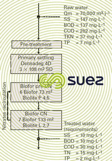
Figure 34 provides an illustration of the arrangement applicable to this system.
- Biofor post-DN :
The Biofor post-DN has to be positioned downstream from a nitrification stage, such as a Biofor N or low loading activated sludge stage. As nitrified water no longer contains any easily biodegradable organic carbon, an external input of carbon will be required (methanol or equivalent). This reagent is combined with the water to be denitrified. This water is fed in through the floor of the reactor. It is compulsory for the amount of carbon used to be governed by the throughflow and by the nitrate-equivalent concentration in order to avoid any methanol excess and also any outflow COD and BOD deterioration.
The following constitute the specific advantages associated with the Biofor post-DN application:
- extremely high maximum hydraulic loading (table 8);
- extremely high denitrified loading, in excess of 5 kg eq. N-NO3·m–3·d–1 for a temperature above 20 °C ;
- a denitrification efficiency of up to 95%.
The main drawback is the need to add a carbon substrate which, save in favourable conditions, will result in high running costs.
Oxyblue : a combination of ozone treatment and biofiltration
Oxyblue treats discharges by positioning itself as a final step before ultrafiltration or reverse osmosis. Under very stringent discharge standards it is used for the final treatment of residual urban water and the treatment on residual industrial water.
In some cases for certain, initially poorly biodegradable industrial effluent, Oxyblue can be implemented.
The process associates the increase in biodegradability of effluent through the controlled contact of non-biodegradable organic material with ozone, combined with a Biofor biofiltration treatment process.
It enables non-biodegradable organic pollutants and persistent micro-pollutants to be drastically reduced in wastewater. Ozone, the most powerful chemical oxidant used in water treatment, initiates and accelerates the breakdown of residual organic matter; it oxidates hard resistant COD.
Biofiltration, integrating fixed biological cultures, then enables biodegradable COD, produced during the ozone treatment process, to be removed.
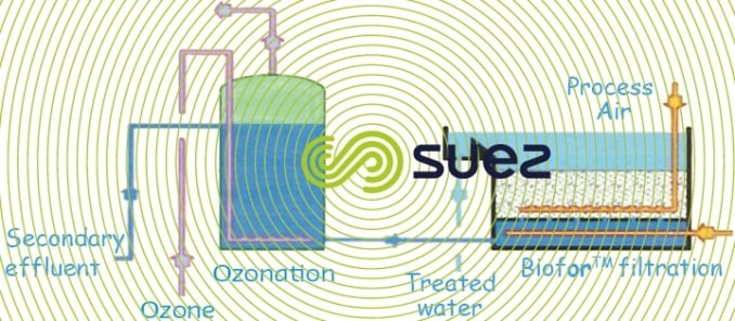
Oxyblue thereby ensures that a removal rate of up to 60% of both COD and trace pollutants is achieved in order to obtain optimal water quality, allowing discharge into sensitive areas and water reuse in cases where an additional fourth treatment process is implemented in the form of ultrafiltration or reverse osmosis.
Oxyblue significantly reduces membrane backwashing reagent consumption (up to 50%) and increases the service life of ultrafiltration equipment.
principales references
Tereos-Syral, Nesle (60), France
- Treatment capacity: 250 m3 /H
- Destination of the effluent: discharge of wastewater
Petrochina, Chengdu, China
- Treatment capacity: 1 600 m3 /H et 400 m3 /H
- Destination of the effluent: Industrial reuse of wastewater and discharge of effluent
Petrochina, Dagang, China
- Treatment capacity: 200 m3 /H
- Destination of the effluent: discharge of effluent and reuse of industrial wastewater
SCA, Laarkirchen, Austria
- Treatment capacity: 2 500 m3 /H
- Destination of the effluent: discharge of wastewater
Bookmark tool
Click on the bookmark tool, highlight the last read paragraph to continue your reading later
