


flotation units – general technology
Reading time:Flotation units can be circular or rectangular. This latter form allows for a harmonious assembly of monoblocs that encompass the flocculator, the flotation unit and the filters while taking up a minimum ground area and is usually reserved for the treatment of high throughputs that are typical of potable water and oil refinery.
From the hydraulic viewpoint and especially with regard to the treatment of water containing high levels of suspended solids and incorporating sufficiently resistant floc, the circular floatation unit prevails over the rectangular version:
- for the same capacity, the distance between the top of the water/air bubble mixing chamber and the base of the scum baffle is less (more vertical water flow);
- an almost uniform bubble distribution can be maintained over the unit’s entire horizontal section;
- it is easier to rake large quantities of sludge.
On the other hand, in drinking water, so as to avoid damaging the (fragile) floc when transferring it from the flocculator to the flotation unit, once again, the rectangular flotation unit with adjacent flocculator proves to be the best solution.
gas used for flotation
The gas used for generating fine bubbles is most often atmospheric air (acronym: DAF, Dissolved Air Floatation), but for industrial water, nitrogen can be used (DNF ) or field gas (fuel gas, DGF) in order to:
- avoid the risk of creating an explosive atmosphere (removal of the oxidant)
- or to avoid oxygenating water (the case of reinjecting produced water)
In this case, with fuel gas being more soluble than air and nitrogen slightly less, the different dissolution rates for these 2 gases are taken into account when calculating the equipment required
general description of a flotation unit
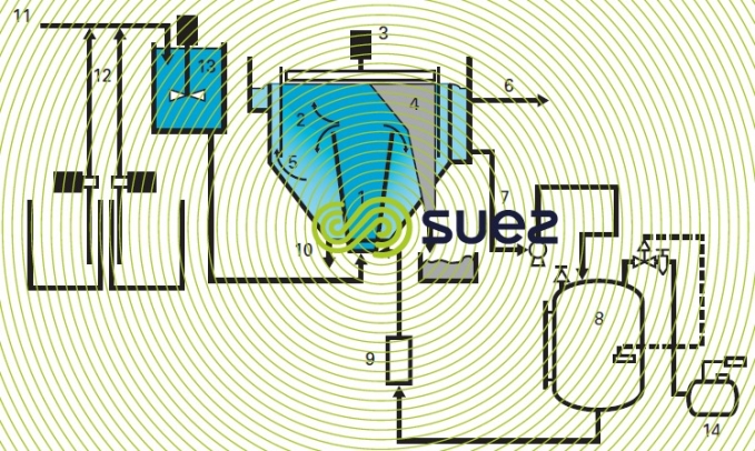
The operating principle described in figure 26 applies equally well to both the circular and the rectangular flotation units;
- the water to be treated (11), previously flocculated using reagents (12) in a flocculator (13) is injected into the mixing chamber (1) where it comes into contact with the pressurised water and is then expanded, resulting in the formation of fine air (or gas) bubbles that attach themselves to the floc. The floc/bubble element has a density that is lower than that of water and is separated in zone (2) before rising to the surface. The sludge formed in this way is collected by a scraper system (3) (or, as an alternative, by overflow) before being removed to a trough (4). The clarified water is collected beneath the scum baffle (5) or a more elaborate mechanism (see clarification flotation units) before being collected and removed at (6);
- pressurised water is obtained (see also microbubble flotation ( DAF or FAD ), figure 35):
- either by recycle pressurisation part of the treated water is recycled (7) and brought into contact with pressurised air (14) in an air saturation tank (8);
- or by full-flow pressurisation: all the liquid to be treated is pressurized.
The pressurized water is injected into the mixing chamber (1) immediately after the pressure relief valves (9) or immediately before pressure relief occurs (nozzles).
In the case of some applications and of large diameters, the flotation unit is equipped with a bottom scraper to make it easier to remove any sludge deposited on the cell floor through (10).
Comments. the mixing chamber has two purposes:
- bringing the water to be treated in contact with the pressurised water after pressure relief occurs;
- dissipating the mixture’s kinetic energy before it is introduced into the separation zone.

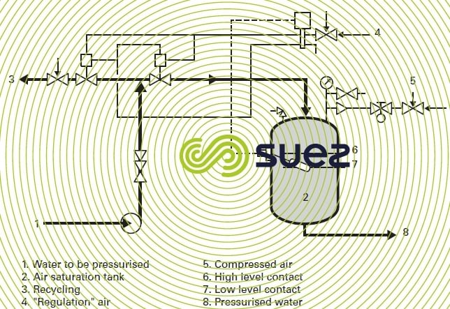
air saturation tanks
Depending on the application, these gas dissolution mechanisms are constructed of protected steel or of stainless steel. They can be vertical or horizontal.
The standard Degrémont® units have a contact time of a few tens of seconds (maximum: one minute) and are vertical for capacities of less than approximately 300 m3 · h–1 of pressurised water.
There are different types of regulation systems (on-off regulation on air or regulation that follows changes in the water flow rate). Figure 27 illustrates the type of layout very often used on grounds of its simplicity.
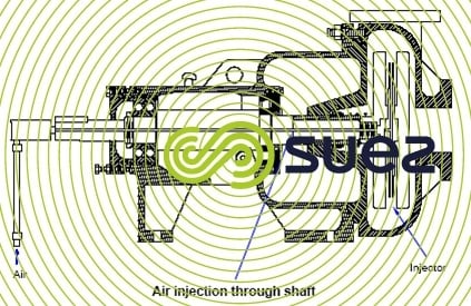
Poseipump© (figure 28)
An alternative for gas saturation tank is Poseipump©. It is a more compact device that can be used to obtain gas-saturated water. A rotating equipment, similar to a pump sucks up the gas to be dissolved through its central axis, ensures gas pressurization and creates significant turbulence to ensure that gas is dispersed into liquid.
In some cases a tank can be added to this device in order to ensure retention time. Its construction is less restrictive than a tank containing compressed gas on a permanent basis.
flotation unit clearance
In some cases, the layer of sludge on the surface can reach several tens of centimetres and be extremely stable (activated sludge thickening). In others, it may be thinner, a few cm thick and/or more fragile (floatation of metal hydroxide floc). Therefore, the scraper-removal system has to be adapted to suit the type of sludge concerned.
The sludge can be removed from the flotation unit:
- by overflow: obtained by a rising water body in the works or lowering the weir
- or it is scraped away: the number of surface skimmer blades depends on their speed of travel, the distance separating two blades and the amounts of sludge to be removed. We must avoid any danger of the sludge becoming degasified or breaking up through too much compression being applied to the scraped cake. This may require the inclusion of several removal channels on the surface of large diameter flotation units.
collecting sludge from the storage pit
Floated sludge to be drawn out of the storage pit may have to be degasified before being pumped out. These pumps must always operate with a positive suction head.
flotation unit cover
The presence of sludge on the surface requires sometimes protection from emission of odors or heavy rain (or strong winds) in order to avoid disturbing the cake and causing part of it to form a suspension again, by a waterproof roof.
Bookmark tool
Click on the bookmark tool, highlight the last read paragraph to continue your reading later
