


sludge blanket settling tanks
Reading time:The basic principle underlying these units has already been described in sludge contact clarification. In this type of settling tank, the sludge formed by flocculation constitutes an expanded mass through which the raw water to be treated, having previously been coagulated, percolates upwards in a regular and even manner. The water flocculates as it travels through the «filtering blanket» formed by the sludge and emerges clarified into the top section of the settling tank.
If water is injected continuously and at a constant flow rate into the base of the sludge blanket, after a certain time, the sludge can be seen to gradually pile up in some areas and, finally, we have a compact mass of heterogeneous sludge through which the water has created preferential pathways. Under these conditions, there is no longer an efficient contact between the water crossing through the sludge blank and the sludge constituting the blanket.
On the other hand, if water is pulsed in, by feeding in water at high flow rates for a very short time, followed by an extended rest time at low flow rates, we find that the mass of sludge continues to remain in a homogenous suspension state. All the sludge is drawn upwards when the water is injected; the energy dissipated creates turbulences that break down the emerging aggregates. However, a period of stillness follows and the water clarifies normally as it would do in a test tube kept absolutely still.
This type of experiment can be carried out in a laboratory to measure the limit rising velocity that can be applied to a sludge blanket: this is a measurement of the sludge cohesion coefficient K (see treatability tests). This limit velocity depends on a number of factors: the nature of the water to be treated, the level of coagulant and flocculent treatment, temperature, the time separating the injection of the difference reagents …
the Pulsator settling tank
Born over half a century ago, this clarifier is the most widely used worldwide for processing natural water; it owes its success to:
- its simple construction and its ability to adapt to all shapes of tanks;
- its high Hazen velocity compared to settling tanks; 2 to 4 m · h–1 in natural water clarification, or even higher with a very favourable sludge cohesion coefficient; this advantage, combined with the absence of a separate flocculator (remember that the actual flocculation and clarification zones are superimposed), produces far more compact plants;
- its operational flexibility; the speed with which it can be commissioned, the low impact of flow rate and/or raw water quality fluctuations (sludge blanket inertia);
- its reliability, especially due to the fact that no mechanical appliances (mixers, scrapers...) are submerged in the water or sludge;
- its reduced operating costs (low electricity consumption, optimised use of reagents …).
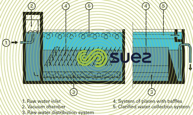
The settling tank (figure 12) comprises a tank with a flat floor through which passes a series of perforated pipes (9) topped by stilling baffles (4) and used to introduce raw water evenly across the entire surface area. In the upper section, another network, made up of perforated pipes or troughs (2) evenly collects the clarified water. This type of distribution system maintains a water flow that is identical at all points throughout the sludge blanket and avoids the danger of dead spots.
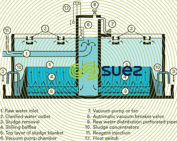

In order to feed the lower collector intermittently, the most cost-effective process consists in injecting raw water through a vacuum chamber (6) in the top of which a vacuum has been created using a fan or blower operating as a vacuum pump (7) and drawing out an air flow that is virtually equal to half of the maximum flow rate of water to be treated.
Under these conditions, the raw water level continues to rise gradually inside the vacuum chamber. When it has reached a level of between 0.60 m and 1.00 m above the water level in the clarifier, an electrical relay connected to a level sensor (float switch (12) or electrode) causes a «vacuum breaker» valve (8) to open suddenly, bringing the chamber into contact with the ambient air. Water then rushes into the clarifier (the stilling baffles helping to maintain an even distribution).
These units are usually adjusted so that the inrush takes between 7 and 15 seconds whereas it takes 30 to 40 seconds to fill the vacuum chamber; the frequency and duration of the pulsations can easily be adjusted if necessary.
The sludge blanket thus undergoes alternating vertical movement and tends to increase in volume because of the suspended solids flocculated in the raw water, captured by the existing mass. In order to maintain a constant clarifier level (5), a certain lateral area of the clarifier is set aside for forming sloping floor pits (10) where excess sludge can be poured and concentrated. These pits are drained intermittently (timers), through ducts (3). One of this mechanism’s major advantages is that, when too much sludge is drained out, this is accompanied by a loss of water that does not affect the sludge blanket.
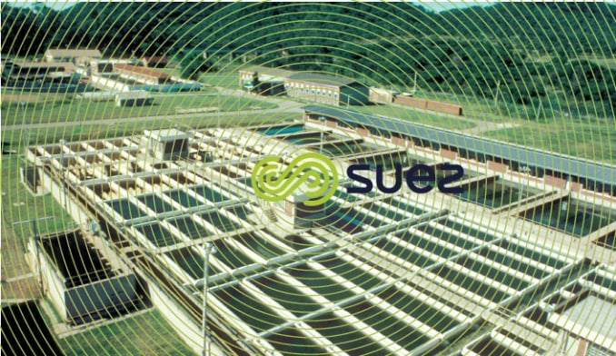
A Pulsator settling tank can easily be constructed in an existing tank (static settling tank, old filter or reservoir). We can thus modernise older plants and multiply the clarification output by a factor of 2 or 3. This type of conversion was undertaken, for instance, in Buenos Aires, Argentina: 864 000 m3 · d–1; in Alexandria, Egypt: 240 000 m3 · d–1…
combination with lamellar settling
Two different approaches can be used to achieve this combination (see also sludge contact clarification):
- either by adding lamellar modules (hexagonal tubes, see lamellar sedimentation and lamellar settling tanks) in the clarified water area; the relevant unit is called a Pulsatube (or Pulsator T);
- or by adding sloping plates within the sludge blanket itself: this is the Superpulsator (or Pulsator S)
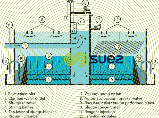
Both principles were subsequently applied simultaneously in the same unit, giving rise to the Ultrapulsator (or Pulsator U); this development is summarised in figure 13.
These units combine the respective benefits of sludge contact clarification, sludge blanket pulsation and lamellar settling (effect on the Hazen velocity and on sludge blanket densification). These units also have points in common (supply, distribution, collection) with the Pulsator whose performance they enhance (permissible velocities, clarified water quality...). All also enjoy the qualities that have already been emphasized in respect of the Pulsator: compactness, flexibility, reliability…
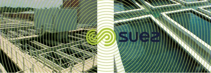
the Pulsatube (or Pulsator T) settling tank (see photos 13 and 14)
Figure 14 constitutes a schematic diagram illustrating this principle:
- if, given an applied velocity that is greater than that enabled by the value of K, fine floc is drawn out of the sludge blanket by the rising flow of settled water, it will be captured by the lamellar module arrangement (12) where it undergoes clarification (because the Hazen velocity has suddenly decreased considerably) and falls back into the sludge blanket. As it falls back down, the floc rolls down the walls of the modules and becomes partially dehydrated and converts into denser and more granular particles. Becoming enriched in this way by sludge having a greater density and cohesion, the sludge blanket can tolerate a higher rising velocity;
- this phenomenon, combined with that of clarified water polishing in the modules, makes it possible to use almost twice the rising velocity compared with the conventional Pulsator (in practice 4 to 9 m · h–1).
If we want to convert an existing Pulsator into a Pulsatube in order to increase the Pulsator’s output, it may occasionally be necessary to modify the raw water and/or settled water distribution systems (increasing velocities and head losses, danger of overflowing …)
the Superpulsator or Pulsator S settling tank
This unit (figure 15) no longer applies the lamellar settling principle merely to clarification but to flocculation-settling by combining sloping plate action and sludge blanket action (see sludge contact clarification). The plates that are submerged in the sludge blanket contribute to good water distribution and, in general, the stilling baffles can be eliminated.
Two phenomena are brought into play at the same time:
- as the water is flocculated, it enters into the system of parallel plates tilted at 60° from the horizontal and perpendicular to the concentrator. The underside of each plate is equipped with baffles that create a mixing motion that encourages flocculation (photo 15);
- additionally, the plates maintain a concentration level in the sludge blanket that is approximately twice that of a Pulsator operating at the same speed.
By combining these two effects, the Superpulsator can double the permissible velocity compared to that of a conventional Pulsator, from 4 to 8 m · h–1 (which performance is close to that of the Pulsatube which has, however, better stability under adverse conditions such as strong sunlight and/or temperature fluctuations).


the Ultrapulsator (or Pulsator U) settling tank
The details provided above enable us to understand that by combining these two principles:
- sloping plates in the sludge blanket;
- lamellar modules above the sludge blanket,
we can improve clarification performances even further. The resulting Ultrapulsator can effectively tolerate a rising velocity that is at least three times greater than that of the conventional Pulsator, usually in the region of 9 to 12 m · h–1.
It is particularly recommended:
- in all cases where a very simple operation is called for while covering a minimum ground surface area;
- for all specific treatment problems (e.g. relatively clear but cold, coloured water such as found in Canada, in the north of the USA or in Russia; pre-treatment upstream from ultrafiltration membranes.
area of utilisation
This type of sludge blanket system can process, in clarification, all types of natural water where turbidity and suspended solids do not exceed approximately 1 500 NTU and 2 g · L–1 respectively (should this not be the case, an appropriate treatment must be included upstream, such as grit removal or desludging) and that tolerate the removal of planktonic micro-algae (up to several hundreds of thousands of units per mL), colour and also clay colloids.
Additionally, sludge concentration and contact time in the blanket being exceptionally high, these units constitute the best support to powdered activated carbon treatment when the water is polluted: the fixing capacity of PAC will then be almost equal to its theoretical maximum level (refer to isotherm = Freundlich isotherm in mechanism and analysis of the adsorbent capacity of a carbon ) and, for the same reduction in OM or micro-pollutants, the treatment rate will be markedly lower than in conventional clarifiers. Therefore, when pollution is merely a temporary phenomenon, it may be possible to do away with a battery of granular carbon filters.
Often selected on the grounds of the many benefits they provide, Pulsator clarifiers or their lamellar derivatives supply water to almost five hundred million consumers in urban areas of all sizes of which some fifty are capital cities; they also supply water to many industrial sites; in all, this type of unit processes between 3 and 4 million m³ of water every hour.
Bookmark tool
Click on the bookmark tool, highlight the last read paragraph to continue your reading later
