


clarification flotation units
Reading time:All these units operate under recycle pressurisation.
circular flotation units
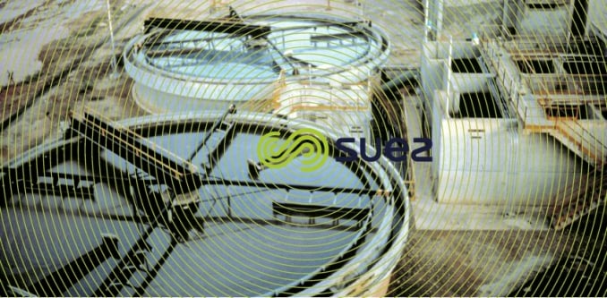
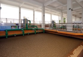
SUEZ use two versions of the circular flotation unit: either a metal version (Flotazur BR) that is available in standard options up to 8 m in diameter (figure 29); or a concrete version (Sediflotazur) that is available in standard options up to 20 m in diameter (please refer to photo 28 for an example of this unit).
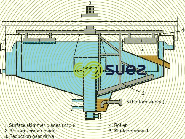

These units are equipped with both bottom scraping and surface skimming mechanisms. Depending on the application, the velocity varies from 2 to 10 m · h–1 and the % pressurised water from 15 to 60%. The number of skimmer blades, and even outlet trough, can be adjusted according to the amount of matter to be removed.
rectangular flotation units
flotazur P (conventional flotation unit)
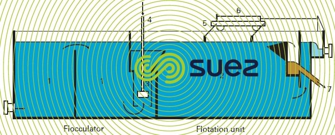
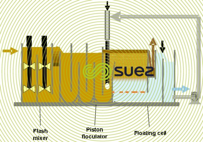
The Flotazur P (figure 30) combines a flocculator (1) with a rectangular flotation unit (2). It is ideally suited to the treatment of lightly laden water, creating a lightweight and fragile floc. The separation rate ranges from 6 to 12 m · h–1 with pressurized water recycling varying between 6 and 12%.
After a 15 to 30 minutes contact time in a flocculator equipped with slow agitators, water is routed direct:
- either into mixing chambers (3) laid out in parallel;
- or into a zone containing a nozzle system,
Where it comes into contact with the pressurised water after pressure relief (4). The floated sludge is extracted through the opposite end (7) by a scraper bridge (5) that shuttles back and forth, skimming off that part of the tank where the sludge thickens (approximately a third or half) without disturbing the expansion zone above the mixing chambers. Depending on tank size, the scraper bridge will be driven either by a pneumatic piston (6) or an electric motor.
This equipment is standardised up to units having a 120 m² surface area and is not usually equipped with bottom scrapers.
high speed rectangular flotation tanks: Aquadaf
special features of the bubble bed flotation cell
This technology emerged as the result of the wish to increase the separation rate beyond 10-12 m · h–1 and thus to reduce structure sizes.
By acting on the hydraulics of conventional flotation units (circulation theoretically across the tank diagonal), various attempts were made to «straighten» these fluid streams; the main lines of development concerned:
a) diffusing pressurised water over the entire flotation surface;
b) using suction headers installed in the cell floor, or a perforated floor, with the aim of collecting water from the entire surface area and not just from one end of the cell;
c) using submerged lamellar systems whose main purpose would consist in trapping bubbles, ensuring that they coalesce and, consequently encouraging them to rise.
Starting with concept b), by empirically improving flotation unit design, we were able to create a real 1 to 2 m deep bubble blanket.
This «bubble blanket», in fact a blanket whose concentration decreased from the top downwards, continues the flocculation process, enhances air bubble/floc coupling and has shown that it produces high bubble-floc aggregate rising velocities by raising micro-bubble rising velocity from 5 to 30‑40 m· h–1 through coalescence and/or agglomeration. These velocities can even be enhanced further by combining concepts b) and c).
The effect of this bubble blanket is comparable to that of the sludge blanket in a Pulsator type unit: inside, flocculation can continue at the same time as the solid/liquid separation is enhanced due to a higher bubble and floc concentration than in the conventional diffused reactor, therefore increasing the likelihood of bubbles and floc coming together. Additionally, «free» bubbles will also coalesce together.
Therefore:
- the shape of a bubble blanket flotation unit will differ from that of the conventional version; the «length» (between the unit’s inlet and its outlet) will be less than its «width» ensuring that the blanket covers the entire volume of the unit;
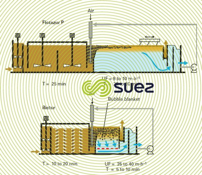
- the preliminary flocculation period can be limited to 10-15 minutes (instead of 20-30 minutes);
- useful velocities will be far higher: 20 to 40 m · h–1 depending on floc properties and water temperature;
- the overflow discharge system is well suited to the shape of the cell (short but wide. A «hydraulic cutter» helps to separate the cake from the wall and limits the amount of water discharged with the cake.
Figure 31 provides an idea of the difference in scale between a conventional flotation unit and a Rictor flotation unit. Therefore, the latter will be the unit of choice for all water of relatively low turbidity, especially surface water sourced from lakes (even when these are eutrophic), coloured water, UWW tertiary treatment and some IWW …
poseidon, a lamellar flotation unit (figure 33)
The Poseidon system which exists in horizontal rectangular configurations (PPM model) or circular vertical configurations (Saturn configuration allowing speeds to climb up to 70m/hour) is an improvement in lamellar flotation by eliminating a tendency of the lamellas to foul. Flocculated water is in contact with fine bubbles and is sent to a pre-separation zone. Only residual floc is sent to the lamellar zone thereby eliminating fouling and enabling higher speeds to be achieved.
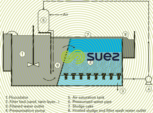
the flotation-filter unit
As the same velocities prevail in a conventional flotation unit and in a filter (5-12 m · h–1), the idea was conceived to use the lower part of the flotation unit as the top of a filter (figure 34): instead of the traditional cell floor, a filtering medium would be laid over a floor equipped with nozzles; a regulation mechanism would be fitted to the filter water outlet (siphon or butterfly valve) to maintain the upstream water level constant regardless of the filter’s fouling.
With this type of unit, it is advisable to have independent units that comprise «flocculator/ flotation cell/filter» because, during the wash sequence:
- the flocculator must not be fed;
- the flotation unit must go into overflow mode (removal of wash water and, if necessary, the sludge cake).
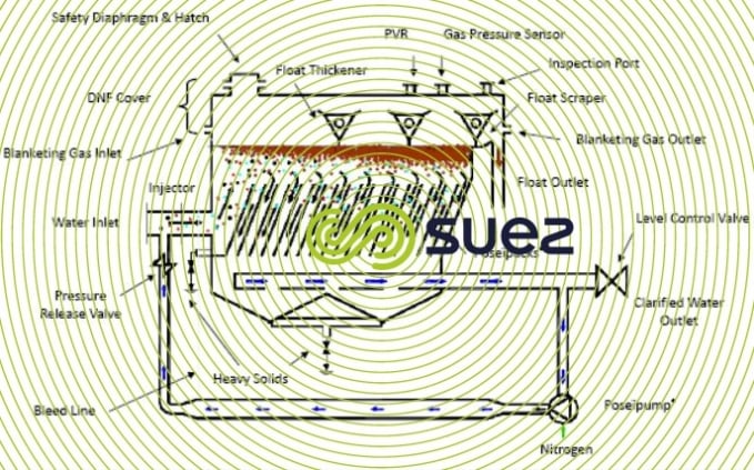
special case of IGF (induced gas flotation)
This equipment is widely used downstream in the oil industry to separate oil from production water.
In upstream oil industry processes, water extracted from the source at the same time as oil is called "production water", and is separated from the oil in a first, three-phase separation phase.
Production water still contains oil particles and IGF was the technology developed to separate them.
IGF processes are less expensive than dissolved gas flotation units. Bubbles are created by emulsion pumps or a pump then an ejector, without a relaxation system . They are often created under pressure. Oil accumulates on the upper surface of the equipment and is removed by opening a valve. In most cases, a retention time of 2 to 4 minutes suffices. The purpose of this is to obtain a concentration level of 30mg/L of oil, often considered as sufficient. If required, a cationic polymer, sometimes specially formulated, can be dosed.
This equipment does not enable a significant amount of suspended matter to be removed.
The SUEZ Oil& Gas Systems company makes this type of equipment.
Bookmark tool
Click on the bookmark tool, highlight the last read paragraph to continue your reading later
