


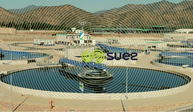
secondary settling tanks
Reading time:These settling tanks are often termed clarifiers and are used in activated sludge systems for separating treated water from biomass, settling sludge and sufficiently thickening it so that when the sludge is returned to the tank inlet, it can maintain the biomass concentration levels required.
Special attention must be paid to the method used to collect this sludge: large amounts have to be collected and the biological nature of the sludge requires tight control over their contact time on the tank floor in order to avoid any unwarranted changes caused by a prolonged lack of aeration.
selecting a clarifier
The choice of clarifier type will be governed more by layout restrictions and flow rates to be processed than by the type of effluent concerned.
circular or rectangular clarifiers?
Rectangular structures, positioned back-to-back if necessary, will produce a more compact layout and fit into a building more easily; however, they generally cost more than circular clarifiers unless the latter have to be covered over
sludge collected by scraping or suction?
Scraped collection is the cheapest solution and ideally suited to the smaller structure; in larger structures, merely scraping the sludge settled on the periphery of the structure back to the central sludge hopper requires a steeply sloping floor and, therefore, deep structures, as well as complex equipment.
On the other hand, suction sludge collection is ideally suited to the larger structures: sludge contact time is controlled and the structure depth limited because the floor is horizontal. In practice, suction clarifiers are preferred to the scraped alternative for diameters over approximately 25 m. In effect, for 25 to 35 m diameters, SUEZ offers an interesting compromise, the Racsuc.
choice of materials
Clarifiers can be constructed of aluminium, stainless steel, painted steel or galvanized steel. The choice will depend on the nature of the water (especially when it contains chlorides), financial conditions and local customs.
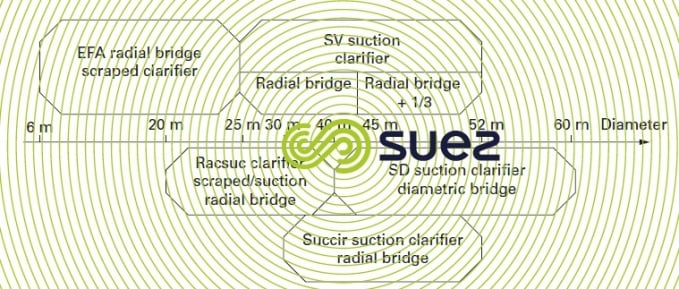
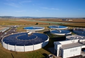
Degrémont® circular clarifiers
SUEZ has developed a wide range of circular clarifiers to meet every need. Figure 21 illustrates their scope.

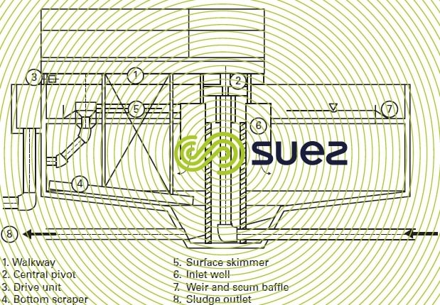
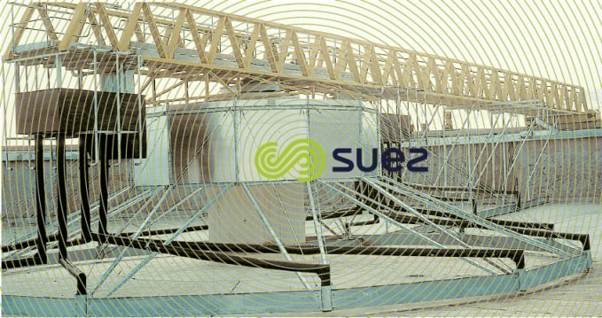
EFA scraped circular clarifiers
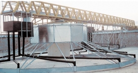
This is a peripherally driven radial bridge: the scraper blade is suspended from a structure that acts as a walkway and that rotates round the tank’s axis (figure 22). The bridge is driven by an onboard reduction gear positioned on the bridge’s outboard end. The structure has a sloping floor and, in the centre, has a pit into which the scraper blade pushes the sludge.
The bridge is constructed in aluminium or stainless steel; diameters range from 6 to 25 m.
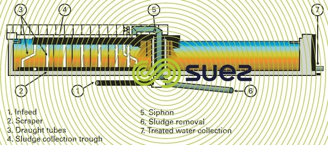
SD, SV and succir circular sludge suction clarifiers
In general, bottom scrapers are mounted on and driven by triangular arms from a support structure; they each take a draught tube; the distance between draught tubes will change from the centre outwards. These tubes emerge into a collecting channel. A telescopic pipe with adjustable discharge level installed on the outlet of each draught tube is used to visually check each output. Provisions may be made to inject air into the straight riser of each draught tube which will then act as an emulsifying pump.
Sludge removal from the moving collection tank to the fixed extraction pipe, forming an integral part of the structure, consists of a siphon with a priming mechanism. These units may also be equipped with surface skimmers for removing scum.
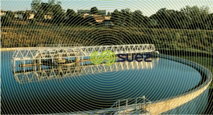
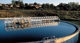
SV clarifier
This is a peripherally driven, radial bridge, suction clarifier that rotates about the central well and that includes a semi-submerged beam set at a lower level that acts as a sludge collection trough (figure 23).
Up to a 40 m diameter, draught tubes are arranged on a radial trough; for diameters over 40 m, the walkway is extended over one third of the opposite radius by a section in overhang, thus increasing sludge collection in the central zone (photo 20).
The bridge is constructed in aluminium, stainless steel or protected steel; diameters range from 25 to 52 m.
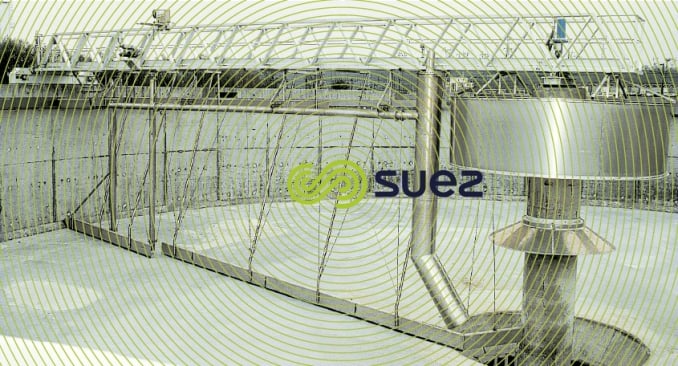
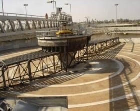
SD clarifier
This is a suction clarifier that has a diametral scraping and sludge collection arrangement driven by a central drive head; the circular sludge collection trough is also mobile. Sludge is collected out of the trough by a fixed double siphon. The access walkway is also fixed (photo 21).
The SD clarifier is particularly well suited to maintaining a reduced sludge contact time in the larger size units.
The bridge is constructed in stainless steel or protected steel; diameters range from 40 to 68 m.
Succir clarifier
This is a peripherally driven radial bridge suction clarifier. The draught tubes rotate with the bridge. In the main, these draught tubes are placed on a circle that is concentric to the structure and positioned at one third of its radius; the remaining draught tubes are in line with the scrapers (photo 22).
When there is no undercurrent, this layout enables good hydraulic performance to be achieved and consequently an excellent quality of treated water to be obtained in terms of TSS.
In this type of appliance, the aim is to achieve a more balanced sludge collection from the central area, a system that is better suited to low sludge index (SI or IB in French) sludge.
The bridge is constructed in stainless steel or protected steel; diameters range from 30 to 52 m.
Racsuc circular scraped/sludge suction clarifiers
This is a peripherally driven, radial bridge clarifier that combines a central zone scraper collection system with a peripheral suction collection system.
The bottom scraper mechanism in the central zone pushes the sludge towards the sludge pit; sludge that is sucked up on the periphery by the draught air lift tubes is transferred to the sludge pit via horizontal tubes and a shaft injects this sludge at slow speeds into the sludge pit (photo 23).
This clarifier complements the scraped and suction clarifier range by retaining the cost-effectiveness of the former and the reduced sludge contact times of the latter.
The bridge is constructed in aluminium, stainless steel or protected steel; diameters range from 20 to 40 m.
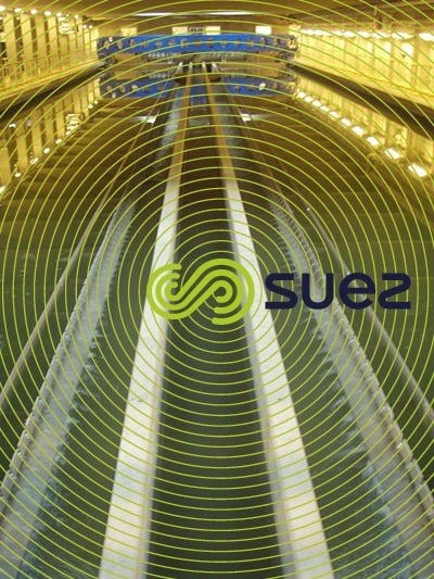
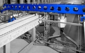
SLG rectangular clarifier
The rectangular shape does not lend itself as easily as the circular version to the construction of structures having extensive unit surface areas. Special attention has to be paid to ensuring that the flow rate is evenly distributed at the intake, to clarified water collection and to the absence of any tank floor areas that escape scraping.
SLG rectangular clarifiers are longitudinal flow clarifiers with horizontal floors.
The scraper mechanism comprises a transverse bridge that automatically travels back and forth. This bridge is equipped with draught tubes. Sludge is extracted using a negative pressure siphon that is mounted on the bridge and that transfers the sludge from the collection tank to a side channel (photo 24).
This construction system can be considered for structures up to 20 m wide and 70 m long.
Bookmark tool
Click on the bookmark tool, highlight the last read paragraph to continue your reading later
