


ultra pure water used in semiconductor and pharmaceutical industries
Reading time:The treatment of ultra pure water (EUP) mainly concerns semiconductor industries and some workshops in the pharmaceutical industry. Given the growing importance attributed to recycling in the former, we felt it would be simpler to include the problems involved in the treatment of effluent and its possible reuse in this sub-chapter.


ultra pure water (EUP) treatment line for the semiconductor industry
general
Water is used by this industry as a rinsing agent during the various phases involved in the manufacture of its components and its quality is of critical importance to the manufacturing process (in direct relation to memory, microprocessor and other product reject levels).
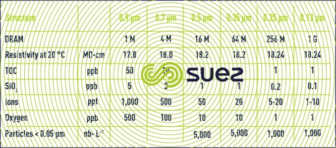
For this industry, water is the essential cleaning fluid and has to be available in large quantities at reasonable costs and this situation must persist. However, as discussed in section process water (table 26), as the components produced tend towards miniaturisation, specifications for elements, both soluble and non-soluble, likely to be found in the water, have become increasingly stringent. These problems face the water specialist with increasingly difficult challenges which, to date, he has been able to resolve.
Also, for the same quality level, when 300 mm silicon wafers were introduced in 2001, this called for a marked increase in EUP flow rates, rising from 4 to 5 m³ for a Ø 300 mm wafer. This development has resulted in the EUP demand from a typical plant to rise to 100-300 m3·h–1.
specifications and treatment design in terms of results
The main impurities to be removed are suspended solids, particles, bacteria, TOC, dissolved oxygen, all ions which include the following causing the greatest difficulties: silica and boron and these, as specified in the extract from table 3 in terms of ppb and up to ppt (1 mg per 1 000 m³) for most ions.
Therefore, treatment lines combine several stages where membranes play an extremely important role.
Figures 13, 14 and 15 show the following systems for a typical plant constructed in Malaysia for 1st Silicon, a 180/130 nm technology FAB :
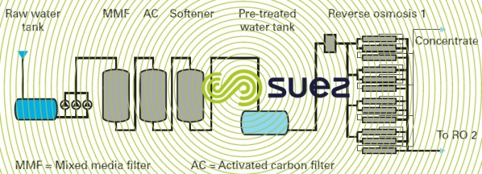
pre-treatment (figure 13)
Water is filtered through a twin-layer filter and then through activated carbon before being finally softened with cationic resin, the latter step in order to limit the danger of fouling and scaling affecting reverse osmosis 1. Clearly, this stage depends on the quality of the available raw water (in this case, surface water).
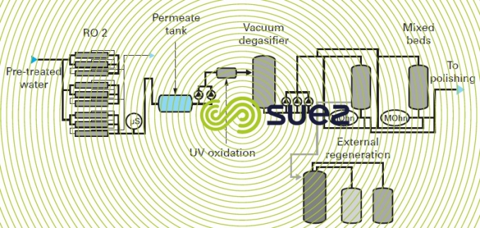
make-up water treatment (figure 14)
This treatment involves a second osmosis working in «2nd pass mode» (see Membrane separation) and which, at this stage, will have eliminated between 99% and 99.99% of virtually all ions, organic matter, particles … The permeate is stored in a tank where it is subjected to ozonization (sterilising and oxidising the OM) before being pumped to the 150 nm UV where residual ozone is destroyed and COT oxidation completed (see Oxidation and reduction). A vacuum de-aerator removes most of the CO2 and oxygen (residual content < 10 ppb). The remaining ions that have passed through the two osmosis units or that have been created by ozone UV oxidation are removed by externally regenerated mixed beds, providing thorough resin regeneration and avoiding any danger of water becoming polluted anew by the regeneration reagents.
Downstream from the mixed beds, we should obtain a conductivity that is very close to the theoretical figure of 0.055 μs · cm–1 (18.2 MΩ·cm–1 at 20 °C).
polishing and distribution loop (figure 15)
This closed loop on the EUP tank (in nitrogen) is used to maintain :
- distribution where water is constantly flowing round, thus avoiding any stagnant points (sites for bacterial recolonisation …) ;
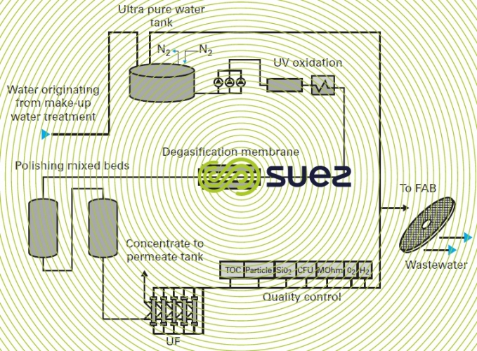
- the quality of this water through a further UV oxidation, de-aeration of the final O2 and CO2ppb through a de-aeration membrane, and then non-regenerating mixed beds installed on this loop.
Filtration through ultrafilters (photo 7) just upstream from extraction points guarantees final particle removal down to less than 1 particle > 0.05 μm per mL. After the ultrafilters, water quality is constantly monitored: at least its TOC, its particles, its conductivity and its silica content.
additional limitations
continuous operation
This is absolutely essential as already discussed because any intermittent operation will cause the physical, chemical and biological quality of the EUP to fluctuate (separating particles, facilitating bacteria recolonisation, compacting and decompacting resins, etc).
modularity
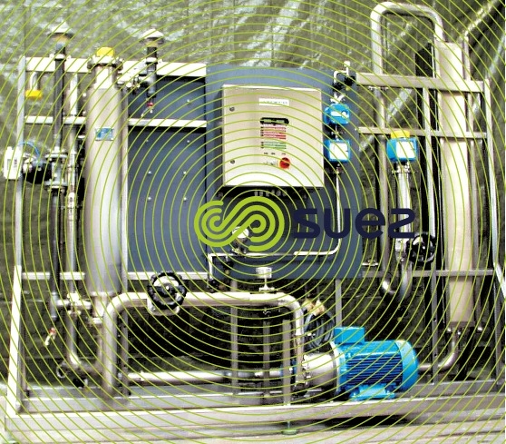
In order to guarantee both continuity of operation and commissioning deadlines, EPU systems must be designed as modular components that are pre-assembled on skids in the factory (photos 6 and 7) and that are as compact as possible with a view to :
- easily ensuring redundancy for totally continuous operation – 0 maintenance shutdowns … (one module of each type on standby);
- facilitating extensions that are often programmed:
- minimising lead time: given the closeness of DRAM prices, producers do their best to minimize the time between the decision to produce a new product (or on a new site) and its launch on the market. Modularity and assembly at the suppliers now constitute two redhibitory conditions. In this connection, we should note the requirement for clean rooms required (photo 8) for assembly, the availability of EUP for rinsing the entire system, of nitrogen for maintaining a nitrogen atmosphere etc.
As time passes, there is every chance that these requirements will become even more stringent which, as far as the selection of treatment tools is concerned, pushes us towards modular tools that can be easily interchanged, easily flushed, led by membrane systems. With regard to the latter, they must be selected meticulously, especially in order to ensure their integrity.


effluent treatment line for the semiconductor industry
general
Originally the poor cousin of EUP, effluent treatment has become increasingly important as the result of more and more demanding discharge standards and also because of the emergence of new types of discharge produced by new production processes which, consequently, make effluent treatment more complicated.
A modern manufacturing unit has effluent that is processed through five systems :
- acid and base effluents;
- effluent containing hydrofluoric acid (HF);
- chemical and mechanical polishing effluent (CMP) containing suspended solids, colloids, etc.;
- CMP effluent that also contains copper;
- effluent containing ammonia and OM.
Depending on environmental restrictions, these effluents must undergo specific pre-treatment and they are then usually neutralised together.
construction example
The ST Microelectronics company (Crolles – France) is equipped with a new treatment system that deals with all the types of effluent listed above.
The treatment scheme used is shown in figures 16 and 17.
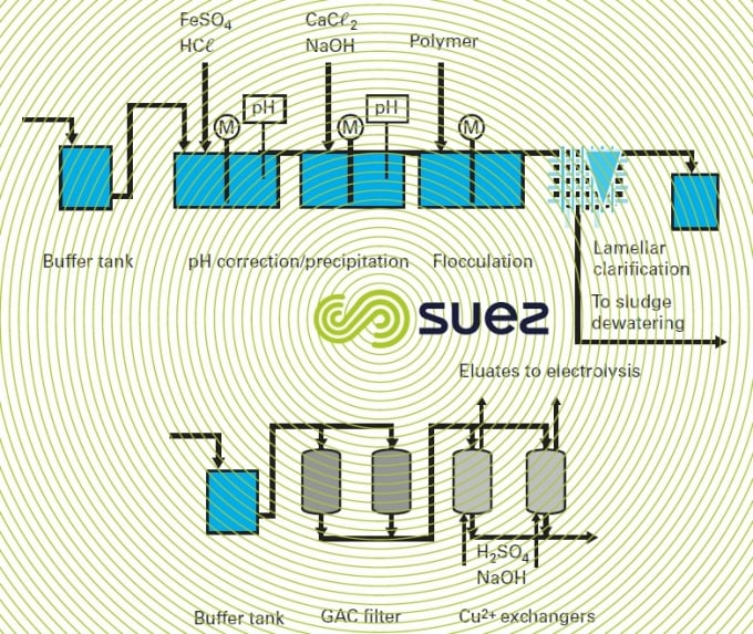
treating CMP effluent that contains copper (figure 16)
by coagulation-flocculation precipitation and separation using a lamella clarifier before removing OM through activated carbon and copper through a selective ion exchanger (Cu < 0.1 ppm).
Comment: Electrodialysis is used to recover copper from regeneration eluates.
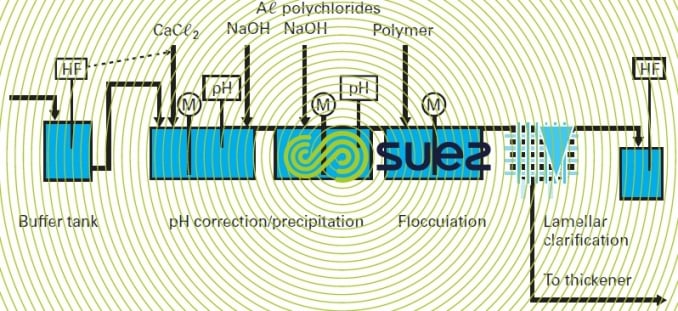
treatment of water containing HF (figure 17)
by precipitating the HF together with phosphates using CaCℓ2 and clarification.
treating water that contains ammonia
using the biological system: Biofors are used to remove the OM (mainly biodegradable alcohol) with NH4+ nitrification and denitrification, or three attached growth stages (see chapters Fundamental biological engineering processes applicable to water treatment et Biological processes). Finally, effluent is combined and sent for neutralization and final safety filtration before being discharged into the river.
recycling – reuse in the semiconductor industry
general
In the semiconductor world, recycling and reuse are open to debate. In fact :
- given the quality demanded, all fear the risk of pollution from wastewater even when the latter has been «properly treated» ;
- additionally, it is clear that a large proportion of EUP, used as a rinsing fluid for low contamination components, has contamination levels that are far lower than those of the available raw water (even in the case of potable water) and that segregating and retreating this rinsing water can prove extremely cost-effective.
It should be noted that only the use of accurate and reliable probes will reconcile the fears of the former with potential savings.
limitations
The above produces the following limitations applicable to recycling treatment:
- processes must be reliable and redundant;
- the quality and availability of EUP must NEVER be jeopardized by risks posed by reuse. This implies, among other things, that any substance that cannot be wholly removed by the main treatment applied to the EUP must be specifically removed before the water is routed to the recycling tank.
Additionally, because of drought conditions, the authorities in some countries have recently imposed up to 85% recycling in order to restrict extractions from the natural environment and have thus obliged us to develop systems that meet this requirement.
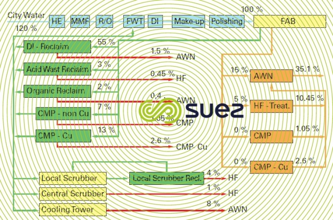
Figure 18 shows the organization and water statement for a plant that recycles over 85% of these effluents. The diagram also shows that the impact made is general and affects all systems. Additionally:
- the levels in residual discharges are obviously higher;
- EUP treatment will be dealing with water that has very different characteristics (far less salt, more particles etc.);
- also, any change to the manufacturing process will have an effect on effluent treatment and, therefore, on EUP and require ongoing dialogue between the producer-suppliers.
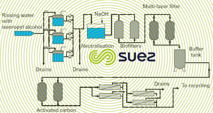
technology
Rinsing water treatment lines, after checking that they have limited contamination, are treated as follows :
- suspended solids and colloids from CMPs are removed through UF membranes;
- ions are passed through ion exchangers (Af – CaF – AF line);
- isopropylic alcohol ( AIP ), the main organic matter present, is removed through a biofilter, usually followed by multimedia, activated carbon and reverse osmosis filtration (figure 19).
Consequently, they can be recycled at the EUP make-up loop inlet.
water for pharmaceutical industries
general
Demand in terms of water quality varies considerably depending on the manufacturing processes involved. We usually have :
- «purified water» (PW);
- «water for injection» (WFI) where quality is set by regulations; GMP standards in Europe, FDA in the USA etc.
It should be noted that this industry has lower requirements for high quality water than the electronics industry, usually between 5 to 50 m3·h–1.
GMP regulations do not apply only to the end quality but also to the means used to achieve that quality which we obtain by using, in particular, pre-assembled reverse osmosis and de-aeration and electro-deionisation systems (see permeation processes and dialysis membranes) that include the materials, sensors and automatic control and monitoring systems required with full certification.
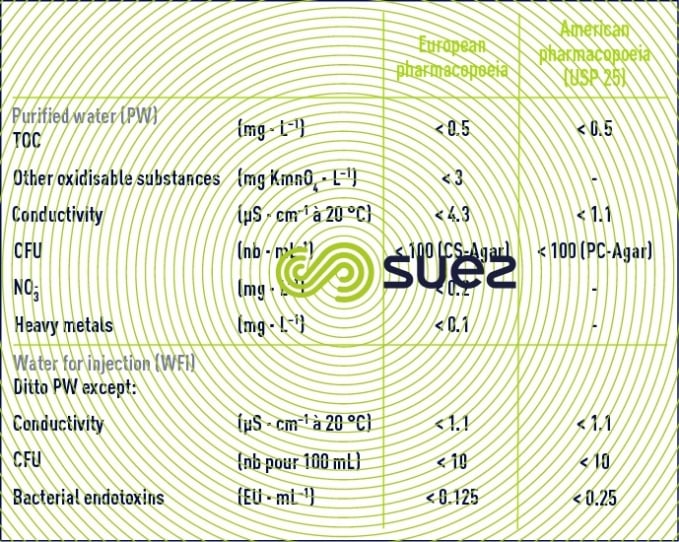
EUP limitations and the pharmaceutical industry
The qualities required and that are, therefore, set by the national Codices (pharmacopoeia), differ slightly as indicated by table 4 which compares the European and the American positions (in both cases, they state that potable water is the raw water used).
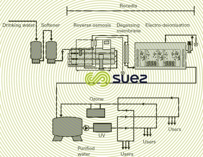
processes used
In order to obtain conductivity of less than 1.1 μs·cm–1, a two-pass osmosis is required with a CO2 de-aeration system. In some cases involving very saline potable water, the second pass has to be replaced by EDI, easily producing 0.5 μS·cm–1. The RO + EDI (Rocedis system) combination investment costs are slightly higher than those of a double pass osmosis system; running costs are comparable. Additionally, because this RO + EDI combination produces water having better conductivity, it is the system that is the most frequently selected.
pre-treatment
The purpose of the pre-treatment is to protect downstream reverse osmosis. It depends on the quality of the potable water used. A softening process using resin is often recommended to avoid scaling or soiling by residual metals (Aℓ, Fe, Mn…) and, in general, dechlorination will be compulsory.
reverse osmosis or RO + EDI combination
Outlet conductivity is affected by two factors, raw water conductivity and TAC. In effect, the dissolved CO2 (pH-dependant) is not screened out by the osmosis membranes. Therefore, we must either operate at a high pH after thorough softening, or use a de-aeration membrane.
Then, a second pass osmosis or an EDI will be required. This second scheme is illustrated by figure 20 where 98% of the osmosis permeate is recovered and is of a quality that is better than 16 MΩ·cm (< 0.065 μS · cm–1), and 2% of the concentrate can be recycled. The EDI (Contipur) energy demand is approximately 20% lower than that of a second pass equipped with low pressure modules. As the CO2 is not properly eliminated by the EDI, we recommend eliminating osmosis permeate via a membrane de-aerator.
The purified water is sent to a distribution loop where oxidizing UV and ozone are used to keep OM and bacteria levels very low.
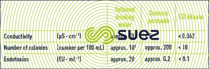
example
A line such as the one described in figure 20 easily allows us to guarantee the figures provided in table 5 where, in particular, we can see excellent figures obtained for endotoxin removal (< 0.1 EU · mL–1) despite an extremely rich potable water (~ 20 EU · mL–1), representing 99% elimination by osmosis and > 50% by EDI. Photo 9 shows a skid in operation.
Bookmark tool
Click on the bookmark tool, highlight the last read paragraph to continue your reading later
