


production of injection water for assisted oil recovery
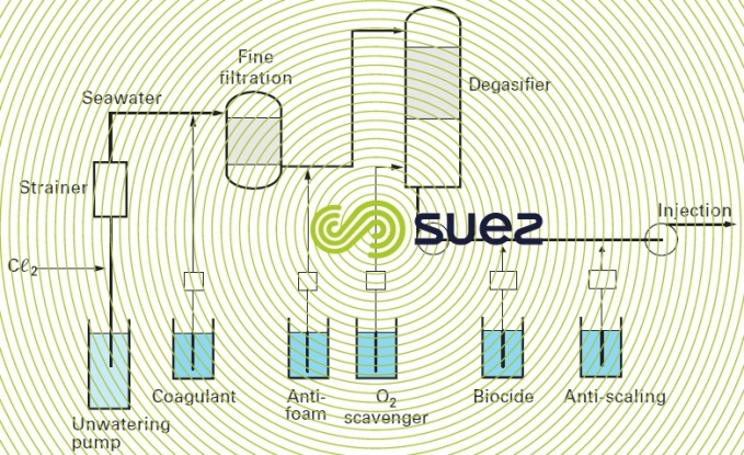
Reading time:As discussed previously (see process water), treatment lines (either formation water extracted with oil, or offshore sea water, or even onshore soft water) must be designed so that water can be re-injected to maintain the well’s pressure and do so without running the risk of clogging (suspended solids or scale deposits, tubing corrosion products, development of micro-organisms). Figure 21 shows assisted recovery seawater treatment on an offshore platform. It comprises :
- pre-chlorination, using the NaCℓO obtained in situ through seawater electrolysis;
- fine straining (100 to 250 μm);
- in-line flocculation (organic and/or mineral coagulant);
- very fast filtration through compact FECM (sand) type or FECB (anthracite and sand twin layer) type granular filters typically eliminating 92 to 98% of particles measuring more than 2 μm;
- water de-aeration, either using a vacuum de-aerator, or gas stripping;
- polishing de-oxygenation using ammonium bisulphate or sodium sulphite;
- bactericidal conditioning;
- if necessary, safety filtration.
Depending on operation options, filtration can sometimes be limited to straining.

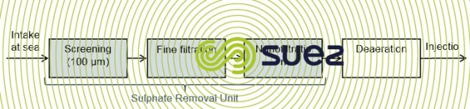
In certain cases and depending up the geological features of the reservoir, sulphates must be removed, particularly when formation water is rich in Sr2+ and Ba2+ ions. This prevents barium sulphate precipitation from occurring and therefore the clogging of source's porous rock. Sulphates may be removed using Sulphate Removal Units (SRU) comprised of a nanofiltration membranes and built specifically for FPSO units or offshore platforms.
These units have the same treatment process :
- intake at sea,
- coarse screening at 100µm,
- fine filtration (either via ultrafiltration, Dual Media filtration or cartridge filters).
- nanofiltration to remove sulphates and to achieve concentration levels lower than 40mg/L.
The diagram below shows a two-stage SRU nanofiltration unit. In this system, the concentrate from the first stage is sent to a second nanofiltration stage. Using a second stage allows the quantity of water treated to be increased and a typical recovery rate of 75% to be obtained.
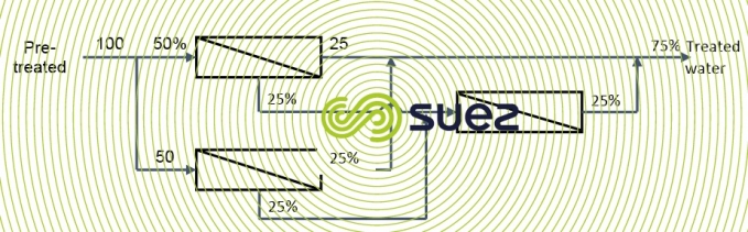
The screens, whose water is used for cooling units and the injection water treatment unit, have a flow rate of 6,600 m3/h. The SRU produces 962,962 m3/h (145,000 BWPD).
The SRU can also be used for assisted recovery processes of EOR oil with low salinity. Thanks to a combination of reverse osmosis seawater desalination and nanofiltration sulphates removal process, injection water's level of salinity can be set according to an oil well's requirements
On land, clarification treatment can be more extensive and include a settling tank, particularly as coastal and estuary waters will often contain silt.
Oxygen de-aeration is carried out when gas effluent can be destroyed by flaring off by in one or more stages. When properly dimensioned, it will avoid subsequent excess consumption of costly reducing agents.

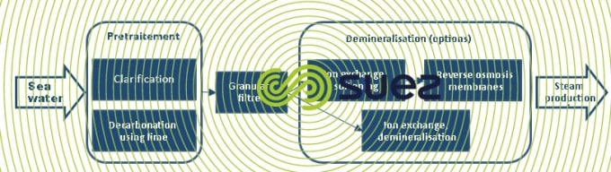
In some cases, very heavy hydrocarbons have to be heated before they can be extracted. We then have to inject large quantities of vapour at 60-150 bar into the oil reservoir rock, involving the use of boilers.
These boilers will be :
- either very high carry-over or very high blowdown (10 to 25%) boilers that can tolerate high salinity water that may sometimes have been softened (TH < 0.05 °F). Depending on the water analysis, this involves the use of a line that includes finishing with an acid regenerated carboxylic acid, or a specific softener resin ;
- or normal HP boilers that, however, require demineralised water and, consequently, as a rule, reverse osmosis and a polishing line (mixed beds or even EDI). It should be noted that, in both cases, when the raw water used is produced from the oil well, it will first have to undergo :
- thorough oil removal of the API-floatation type followed by filtration ;
- often silica removal. In fact, this water is often rich in dissolved and/or colloidal silica. Silica removal (see Chemical precipitations) will often be combined with a softener (lime or lime + CO3Na2…).
As with all recycling, thorough knowledge of the quality of the raw water will govern the choice of recycling treatment and guarantee uninterrupted production of the vapour essential to the field’s output.
Bookmark tool
Click on the bookmark tool, highlight the last read paragraph to continue your reading later
