


cooling circuits
Reading time:circuit components
An industrial cooling process has two phases :
- heat to be removed is transferred to a cooling fluid through direct or, more generally, indirect contact by means of heat exchanging equipment:
- calories are released from the cooling fluid into the environment.
The main items of equipment used for cooling purposes are :
- condensers and heat exchangers;
- oil, air, gas en liquid coolants;
- motors, compressors;
- blast furnaces, kilns, rolling mills, continuous casting, converters;
- chemical reactors.
The behaviour of this equipment will depend on:
- its construction type (tubes, plates…);
- the water circulation system (internal, external, velocity…);
- metals in contact with the water (steel, stainless steel, copper and its alloys, aluminium, etc.);
- materials used (concrete, wood…) in the circuit’s construction.
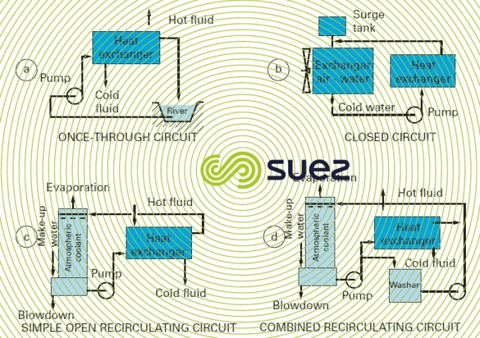
There are three possible cases (figure 16); hot water:
- is discharged direct into the sea, river or drains: this is a once-through circuit;
- is cooled through contact with a secondary fluid (air or water) and returned to the equipment to be cooled without coming into contact with the air: this is a closed circuit;
- is cooled through partial evaporation in an atmospheric coolant before being returned to the equipment: this is an open recirculating circuit.
Once-through circuits (figure 16-a) requiring large quantities of water and creating major "heat pollution" are now often restricted to older systems or to systems using seawater.
In closed circuits (figure 16-b), i.e. closed and without evaporation, very little make-up water is required (leaks) but this system has a limited thermal efficiency. That is why these systems are mainly used on smaller circuits or on special applications.
Therefore, open recirculating circuits (figure 16-c) are the most widely used because they have less of an impact on the environment than once-through systems and are more cost-effective than closed systems.
There are also so-called combined open recirculating systems (figure 16-d) where water can also come into direct contact with pollution created by the processes (e.g. gas scrubbing).
open recirculating circuits
Figure 17 repeats figure 16-c but details the various water flows involved and which, in conjunction with heat parameters and concentration levels, are characteristic of this type of circuit :
V(m3), total volume of water in a circuit constituted by :
- hot water tanks;
- cold water tanks;
- heat exchangers;
- connecting pipelines …

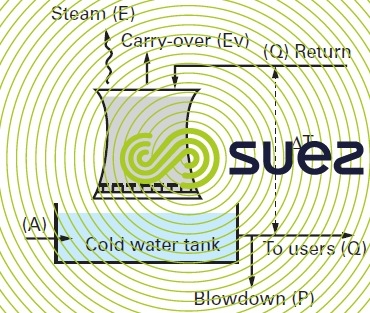
Q(m3·h–1), hot water circulation flow returned to the coolant.
ΔT(°C), temperature difference between water entering into and discharged by the coolant.
T max.(°C), temperature of the water film («skin» temperature) in contact with the circuit’s hottest wall.
W(kcal·h–1), atmospheric coolant efficiency; this efficiency is expressed as the product of the two previous values :


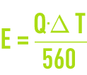
E(m3·h–1), evaporation flow, i.e. the amount of water evaporated in order to cool flow Q.
This evaporation flow consists of pure water that does not contain any dissolved salts. Supposing latent vaporisation heat of 560 th·m–3 (2 340 MJ·m–3), we have the following theoretical equation :
As the air taken into the atmospheric coolant (700 to 1,000 times the water flow) heats up in contact with the water, it also contributes to the release of calories. Therefore, the following equation :
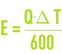
is closer to reality.
Ev(m3·h–1): drift loss flow. This is the water entrained in the air flow in the form of droplets. Therefore, this flow consists of water which, when analysed, produces the same results as the circulating water.
Constructors aim to reduce this drift loss as much as possible. It is currently equal to approximately 0.005% Q but, in practice, the following equation is often used as it allows for lack of drift eliminator maintenance:

D(m3·h–1):total deconcentration flow calculated in such a way as to maintain a maximum permissible concentration of dissolved salts. In the absence of any leak and to avoid precipitation and/or corrosion, a proportion P of the circulation water needs to be blown down in addition to water loss Ev such that :

A(m3.h–1): make-up water flow.
The make-up water flow must compensate for all water losses throughout the circuit: total deconcentration and evaporation.

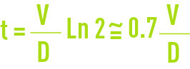
t(h):dwell time t at the end of which the concentration of an injected reagent t(h): dwell time t at the end of which the concentration of a reagent injected has reduced by half under the effects of the blowdown:
C: concentration level. This refers to the ratio between the levels of dissolved salts found in the water circuit S and in make-up water s (but also the ratio of the make-up flow over the total deconcentration flow as seen earlier).
Similarly sA = CsD whence A = CD thus:

quantities of water used
electricity generating station condenser cooling
Examples:
circulation flow rates
- 16-17 m3·s–1 for a conventional thermal power plant operating at full load (500 MW), T = 8.4°C;
- 46-47 m3·s–1 for a nuclear power station operating at full load (1,300 MW), T∆=12.6°C.
make-up and open recirculation systems
With a 3 to 4 concentration level and depending on air hygrometry:
2.4 to 3.6 m3·h–1 per MW.
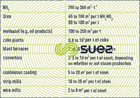
various cooling systems used in industry
The following table provides some idea of the magnitudes of circulating volumes for certain processes (excluding gas scrubbing) (table 21).
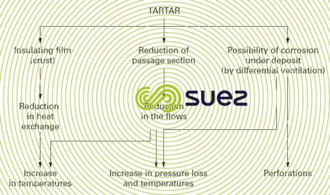
drawbacks created by tartar
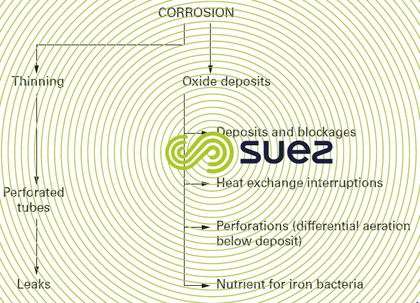
drawbacks caused by corrosion
The half-opened circuit is commonly used, but evaporation in the circuit causes concentration in water to occur, thereby concentrating the potential pollution in make-up water (suspended, colloidal or dissolved solids, micro-organisms, atmospheric pollution) as well as dissolved salts which may cause scaling. These disadvantages as well as the methods to resolve them are explained in more detail in chapter Treatment and conditioning of industrial water.
Bookmark tool
Click on the bookmark tool, highlight the last read paragraph to continue your reading later
