


industrial applications
Reading time:general installations
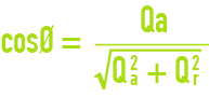
calculating an installation’s mean cos Ø
If Qa is the active energy consumption read on the active metre for a given period of time and Qr the reactive energy consumption read on the reactive metre for the same period, the installation’s mean cos Ø over this period will be provided by the following formula:


improving the cos Ø
As the line losses through the Joule effect are proportional to l2, while active energy consumption is only proportional to I cos Ø, distribution sectors will penalise users who have a power factor that is below a certain value (approximately cos Ø = 0.93 equivalent to tg Ø = 0.4 on a French mains system.)
When a cos Ø reduction is caused by a self-inductive reaction from the installation, cos Ø can be improved by using a bank of capacitors. The capacitor bank’s power expressed in kilovar required to increase cos Ø to the requisite value, can only be accurately calculated after the water treatment plant has been operating for 4 to 6 months.
However, in order to compensate for a temporary poor power factor, it is possible to install a bank of capacitors having an estimated value equal to approximately 10% of the plant’s total installed power.
asynchronous motors
The motors normally used are asynchronous motors; the information given below applies exclusively to this type of motor.
rated power input power
The rated power is the one featured in the catalogue or on the motor data plate. Rated power is the mechanical power applied to the motor shaft and expressed in kW.
The following equation provides the electrical input power :

Input power can also be expressed in kW and it is the power that is used to establish the installation’s power statement.
A motor must be used with the frequency defined by the constructor. A motor designed to take 50Hz will produce a lower torque if supplied from a 60 Hz power source.
efficiency
Mass produced motors have an efficiency r that rises with the motor’s power.
Example :
- 50 kW motor r = 0.85;
- 1 kW motor r = 0.70;
For a given motor, the efficiency quoted by the constructor refers to full-load operation; it will drop slightly with the load.
Example of a 50 kW motor :
- ρ = 0.85 at 4/4 load,
- ρ = 0.82 at 3/4 load,
- ρ = 0.80 at 1/2 load.
calculating a motor’s power
To determine a motor's rated power, it is recommend to use, taking into account the mechanical power absorbed by the driven unit, the following margins (save in special cases, such as crushers, comminutors):
- 10 to 15 % for direct coupling;
- 20 % for belt transmission.
supply voltage
- Power varying more or less as the square of the voltage, it is essential that the motor must be appropriate to the exact voltage delivered by the mains.
For instance, a motor delivering 15 kW shaft horsepower for a 380 V voltage, will only deliver approximately 12.5 kW for a 350 V voltage.
- Most constructors provide a six-terminal box (figure 47) for star connection (figure 48) and for delta connection (figure 49) by moving terminal strips: for example, the first will be used with 380 V three phase current and the second with 220 V three phase.


If the motor has to start in star delta mode, the six terminals must be taken out and used for the following voltages (table 76) :
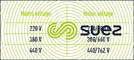
No connecting strips should be placed in the terminal box for this type of start.
no-load asynchronous motor speeds
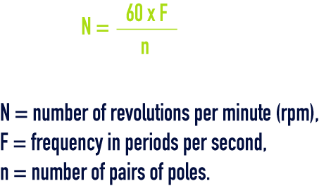
Single or three phase asynchronous motors have a no-load speed that is virtually the same as the synchronism provided by the following formula :
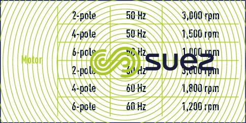
Example (table 77) :
Under load: speed is slightly lower than the no-load speed. The difference corresponds to the slip that is expressed by the relation:
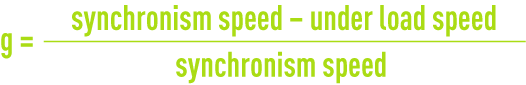
g lies between 2 and 8% of the synchronism speed.
choice of motor and start mode
These two issues depend on the equipment driven and on requirements imposed by the utility.
As far as the driven equipment is concerned, regardless of the start mode, the accelerating torque (difference between the drive torque and the resistive torque) must be enough to ensure that the unit is brought up to speed. Two main factors are involved :
- the gyration moment, Gd’, expressed in Newtons per square metre;
- the torque required for the machine to start up.
Some machines start with virtually no load load (fans, for instance) but the weight and diameter of the rotating components (elements that are characteristic of the Gd’) are such that they require relatively high levels of energy, converted almost exclusively into kinetic energy, in order to come up to speed.
With regard to other machines (comminutor pumps, compressors), as soon as power is connected, the motor must allow these units to develop mechanical work while increasing their speed; therefore, the starter torque must therefore be taken into consideration in these cases.
«Direct across-the-line» starting is normally recommended :
- equipment brought up to speed faster;
- overall heating reduced.
This is feasible when :
- the mains capacity is adequate;
- the driven machine has to withstand mechanically the starting torque.
In the case of an emergency circuit, the power available will be limited and, in most cases, gradual starting modes have to be used.
Table 78 provides the characteristics of the different starting procedures.
Direct current:
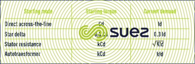
k is the starting torque coefficient selected.
Current demand/starting torque ratios, for nominal values, have been provided in table 79 (approximate values).
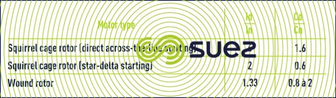
Id = starting intensity,
In = nominal full load intensity,
Cd = starting torque,
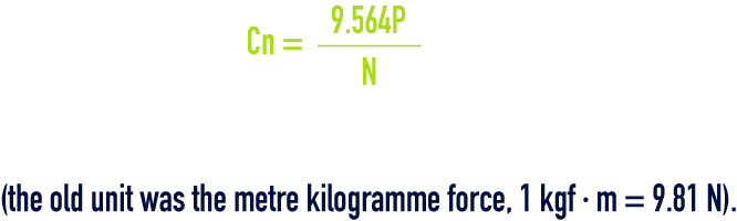
Cn = nominal torque,
Cn is expressed in Newton-metres. If N is the speed in rpm and P rated power in kilowatts :
current input


Pn is the motor’s rated power expressed in kilowatts.
approximate figures for current input (case of a 1 to 10 kW motor)
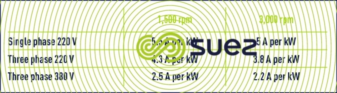
For a given power, the cos Ø and efficiency will drop off as the number of poles rises, the current input will rise, for a given power, as the nominal speed drops.
Thus, a 750 rpm–1 motor will absorb 20% more than a motor of the same rated power at 3 000 rpm–1 and 10 % more than a motor of the same rated power at 1 500 rpm–1.
power cables
As the permissible voltage drop at a motor’s terminals at full load is 5%, the power supply cable section must be calculated accordingly, particularly bearing in mind the current input at full load and the cable length.
For information, table 81 provides the characteristics of the power cable for a 380 V three phase cable having a maximum length of 25 m together with the diameter of the stuffing box used on the terminal box.
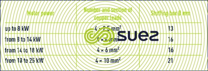
The fourth lead can be used to connect the motor to earth and this is normally done inside the terminal box. It is forbidden to use an anchor bolt to earth a motor.
Do not forget that two cables are required for star-delta starting. Both leads can have the same section. One of the cables must have a fourth lead used to connect the motor to earth.
permissible line voltage drop
The NF C 15.100 standard sets the voltage drop to a figure equal to a percentage of the mains voltage.
- 3% for lighting distribution systems;
- 5% for power distribution systems.
On motor start-up, a 10% voltage drop for power distribution systems is normally regarded as acceptable.
subscription – electricity supply contract
The power supply contract has to be negociated on the basis of the simultaneous input power taken off the mains network, if necessary after optimisation, based on the different hourly bands offered by the power supplier.
In effect, depending on the season, these suppliers will offer a range of tariffs based on the hour bands during which energy is consumed, with cost differences that can range from one to three or even four !
Therefore, before doing anything, a thorough knowledge of local price structures is essential and an operating statement must be drafted.
Bookmark tool
Click on the bookmark tool, highlight the last read paragraph to continue your reading later
