


calculation of systems reducing pressure
Reading time:

rough calculation


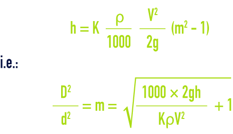
where :
h = the negative pressure created by the device, in metres of water at 4°C (density 1 000 kg · m–3),
K = experimental coefficient (in the region of 1)
ρ = fluid’s density under real flow conditions, in kg · m–3,
V = fluid velocity at device intake in m · s–1,
g = gravity acceleration 9.81 m · s–2,
D = pipe diameter, in m,
d = diameter of the liquid stream at maximum throttling, in m,
m = ratio between the pipe section and the section of the liquid stream at maximum throttling.
diaphragm head loss (for Re > 105)
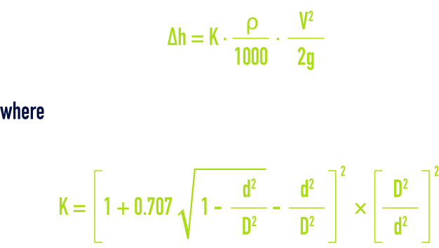
for a sharp edged diaphragm [sic] where the aperture diameter d is expressed using the same unit as the internal pipeline diameter D.
precise calculations of a measurement system reducing pressure
Refer to standards ISO 5167-1 to ISO 5167-4.
installation conditions
Diaphragms, nozzles and venturi nozzles must be mounted on a straight pipeline where the length of the upstream portion is equal to at least 10D and the downstream portion length greater than 5D, these minimum figures being increased in the case of slight throttling. In the case of the classic venturi, the minimum upstream straight section is only 1.5 to 6 D, depending on the amount of throttling (ISO 5167‑1 standard).
The length of the venturi tube is established standardised coefficients (see standard above) and by the choice of constriction D - d.
Bookmark tool
Click on the bookmark tool, highlight the last read paragraph to continue your reading later
