


water head losses through friction in the pipelines
Reading time:empirical formulae
Many authors including Prony, Flamant, Darcy and Lévy, have put forward empirical formulae for calculating these head losses; these formulae are based on a certain number of practical tests using pipe and joint types that no longer form part of modern productions. Furthermore, these formulae had limited application, and did not reflect the physical reality of the phenomena and the results obtained were sometimes very approximate. Therefore, for the above reasons, these formulae are no longer used.
The Williand and Hazen empirical formula, although quite old, is still being used in the USA. It has the following form (in metric units) :


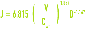
the coefficient Cwh varying with pipeline diameters and with the condition of their internal surfaces.
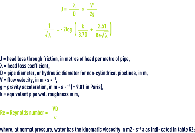
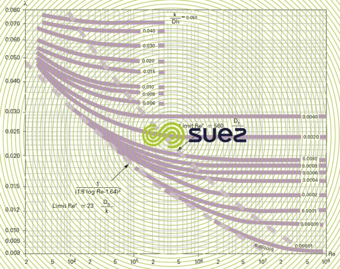
colebrook’s formula derived from Nikuradze’s experiments
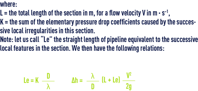
where :


choice of roughness
The accuracy of results in friction loss calculations depends on the initially selected roughness coefficient. In the case of pipelines carrying water, this choice will be linked to both the nature of the pipe walls, to their changes over time and to the physical-chemical properties of the water carried.
- Non corrodable smooth pipelines and unlikely deposits
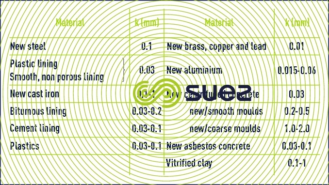
These conditions will be met with water that is not loaded and that is carried through pipes made of plastic, asbestos cement, centrifuged cement or made of any non-corrodible material or having a smooth lining. In practice, k = 0.1 mm will be the applicable roughness in view of the inevitable minimum deterioration that will take place over time, although k = 0.03 mm will be theoretically accepted in new pipes. For all usual materials, roughness k figures are those provided below, applicable to average utilisation conditions, inclusive of joints (table 53).
- Corrodible pipelines and likely deposits
When such pipes carry relatively aggressive, corrosive, scale-forming or laden water, it is accepted that mean roughness will reach approximately k = 2 mm. In low aggressivity, low scale-forming non-chlorinated raw water, this coefficient becomes k = 1 mm. In lightly laden raw water and filtered water that is neither aggressive nor scale forming and that has undergone anti-algae treatment, k = 0.5 mm is permissible.
In average water quality conditions, as a first approximation, for the value J applicable to pressure drops as given in the following tables, we can also use the arithmetical mean of the figures entered in the “new pipeline” and “fouled pipeline” columns.
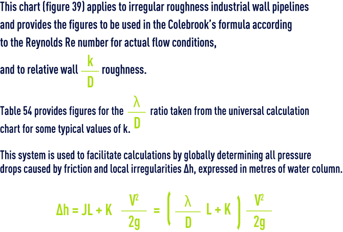
calculation using the universal chart

pipelines of various shape
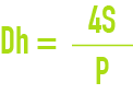
In order to apply the above formulae, we need to use the concept of hydraulic diameter Dh which is the diameter of the equivalent cylindrical pipe.
If S is the pipeline section and P its perimeter :
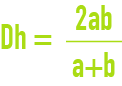
For a rectangular section pipeline having measurements a and b :
partially full circular pipelines
Let :
- q (L·s–1) be the flow discharged by a diameter D pipeline having a gradient p (mm · m–1) and filled to X% of its diameter;
- Q (L·s–1) be the flow discharged by a diameter D pipeline delivering at full section with a head loss (mm.m-1) equal to the gradient.
If we know D and p (and, therefore, Q), the flow rate q we are looking for will be provided by :

m being provided by table 55 as a function of X.

Bookmark tool
Click on the bookmark tool, highlight the last read paragraph to continue your reading later
