


water flow through channels
Reading time:empirical formulae used to calculate pressure drops caused by friction
Only the following formula are routinely being used to calculate pressure drops caused by friction; the Manning-Strickler formula tends to be widespread due to its simplicity and its generalised application to all uniform forms of flow in channels or rivers.
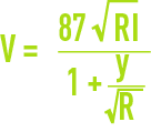
Bazin formula


Manning‑Strickler formula
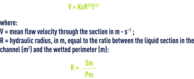
I = canal gradient, in metre by metre:
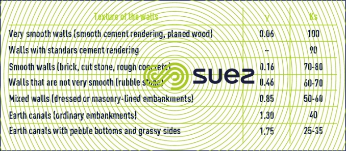
γ and KS = wall unevenness constants.
The wetted perimeter is the total contact length between the fluid and the canal walls along a given section.
The texture and consistency of the walls can restrict the maximum permissible velocity in the vicinity of these walls.

The critical flow is reached in a rectangular section channel that has a width L and a water depth Hc such that Q2 = gL2H3c for a flow rate Q, that is, a critical velocity:

At higher velocities, we have a torrential flow: this flow obeys complex laws and must be covered by special studies (mathematical models, mock-ups …). Below this limit, the flow is said to be fluvial with H > Hc and V < Vc. In water treatment works, flow will most frequently be of the fluvial type; the two earlier inequalities will, therefore, have to be verified.
In uniform fluvial flow modes, wetted section and velocity will be constant in the successive profiles, the friction loss being exactly compensated by slope.
The Bazin or Manning-Strickler formula linking velocity, hydraulic radius and slope, make it possible to calculate one of these values if the other two are known, i.e. three of the following four parameters: flow rate, wetted section, wetted perimeter and slope.
Starting from the normal equilibrium defined in this manner, local level rises or surges caused by flow being brought up to speed or by restitution of energy generated by irregularities, have to be calculated.
In water treatment works where straight lengths are generally short, level variations through irregularities have a high relative significance.
using the universal calculation chart
This calculation chart (figure 39) providing the pressure drop coefficient l caused by friction, also applies to channels that have walls of irregular roughness. For concrete channels, the roughness coefficient k will be, on average, between 0.5 mm (smooth render) and 2 mm (unsurfaced exposed concrete under average conditions). The calculation method is the same as the one for pipelines (water head losses through friction in the pipelines) using the hydraulic diameter :
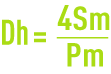
Sm being the section of the channel filled by water and Pm the wetted perimeter, expressed in m² and m respectively.
calculating minor losses
Calculations are carried out in the same way as for pipes (minor losses in the pipelines, fittings, valves… for water), starting downstream and for the uniform fluvial flow velocity obtained. Local upstream upsurges reflect pressure drops in conduit irregularities.
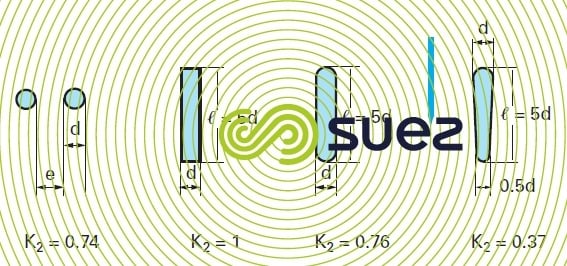
pressure drop through a screen
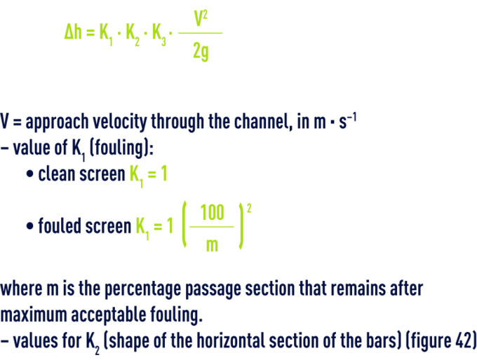
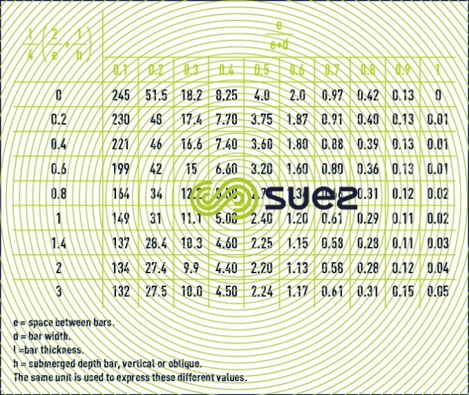
- values for K3 (section of gap between bars)( table 69).
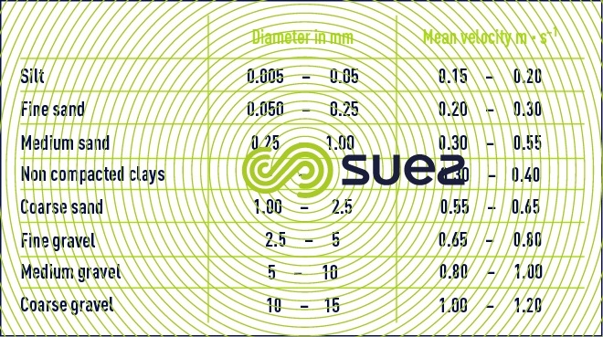
dragging velocity for some materials
- 1 m water depth, straight canals
- Corrections for other water depths
Bookmark tool
Click on the bookmark tool, highlight the last read paragraph to continue your reading later
