


flue gas treatment types
Reading time:There are three main groups of processes: wet, dry or semi-wet. These major groups have a few “hybrid” offshoots.
the wet process
This process is based on the flue gas iso-enthalpic expansion in order to bring these fumes into the presence of water at saturated conditions. Under these conditions, the cooled and saturated flue gases will be subjected to a series of treatments designed to transfer the pollution agents from the gas to the liquid phase. The purified gas phase might be discharged in accordance with regulations; the liquid phase must be treated either specifically or by returning the liquid phase to the plant inlet provided that this is an acceptable option.
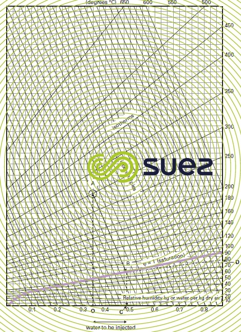
Its operating principle is based on the wet air diagram (figure 39). The simplified process is described below :
- the relative humidity of the flue gas to be treated is first established and expressed as g H2O· kg–1 of dry flue gas (e.g. 0.35) (point O);
- vertically up from this figure, we have a point A which refers to the temperature entering into the wet system (e.g. 300 °C) and, from this point, we drop down to the saturation curve (φ = 1) along a line that is parallel to the iso-enthalpies (point B);
- at the intersection with the curve φ = 1, we drop down along a vertical line to the X-axis in order to determine saturation humidity (point C);
- the difference between the saturation humidity figure and the original relative humidity provides the amount of water that has to be injected into the system per kg of dry flue gases (OC);
- from the saturation point (B) on the curve φ = 1, we plot a line parallel to the isotherm curves in order to establish the saturation temperature applicable to these flue gases (point D).
The saturation process described is carried out in a quench chamber into which saturation water is injected with a slight excess; the process is continued with two washers (tray or packing strainers) each equipped with a recirculation loop and the appropriate blowdown and make-up.
The advantage of the wet system is that it can be accessed at high temperatures, e.g. immediately after the fluidisation air preheating exchanger. Obviously, in such cases, the subsequent recycling of waste heat from flue gases is no longer an option. Figure 40 provides a description of this system.
It addresses the various forms of pollution as follows :

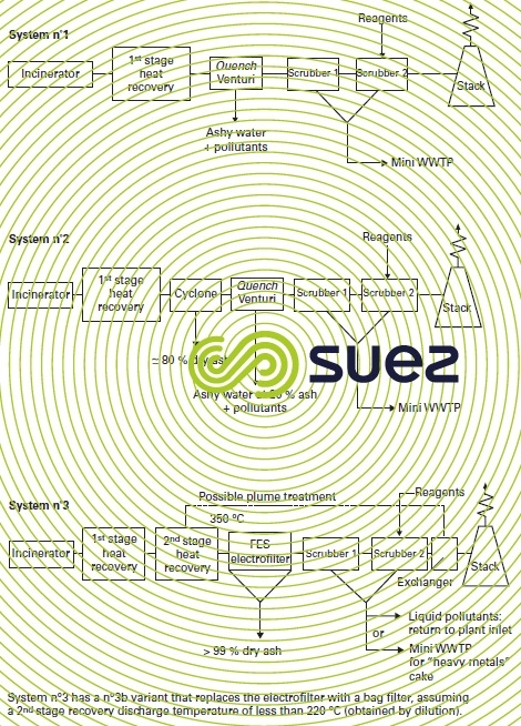
dust
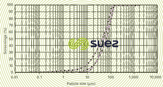
Dust is mainly processed by trapping it in water droplets that are violently agitated as the result of the venturi quench head loss. This head loss must follow the particle size curve for the duct concerned (figure 41 defines their typical domain). This curve defines a wash water flow obtained by internally recycling approximately 10 times the theoretical saturation flow rate (represented by the OC segment in figure 39).
For use in fluidised bed applications (average dust content of 30 g ·Nm–3) and given that the product discharged into the atmosphere is subject to a statutory maximum of 10 mg · Nm–3, this means that the venturi alone must have a better than 99.5 % abatement efficiency. This is only feasible with head losses greater than 100 mbar. Should this not be the case, additional treatment will be required either via a wet electrostatic precipitator, or via preliminary dust removal, or via a cyclone or a hot electrostatic precipitator (see systems 2 and 3 in figure 40); the latter solution will also limit the amount of “ashy” water that has to be sedimented and removed.
halogen pollution (Cℓ– and F–)
This pollution is easily eliminated in the wet system (venturi quench and scrubber due to the high Cℓ–et Fℓ–anion solubility. On the other hand, this means that the wash water loop, centered on the venturi and the first scrubber, has very strong acid properties that have to be allowed for when selecting the equipment and construction materials. This acid loop must eliminate most of the HgCℓ2 and also the acidity level has to be adjusted by deliberately adding HCℓ.
sulphur pollution (SO2, SO3)
Preference should be given to treating sulphur pollution with a diluted sodium hydroxide backwash (scrubber 2). Lime can be considered but has the drawback of requiring the preparation of lime slurry and of causing greater scrubber scaling problems. SO2 reduction efficiency will depend on the pH which, therefore, has to be adjusted on the basis of the emission objectives.
volatile heavy metal pollution
On the assumption that the quench-venturi-scrubber system will not guarantee 0.05 mg ·Nm–3 emissions due to the presence of particulate Hg, this treatment has to be supplemented :
- either by including a wet electrostatic precipitator;
- or by inserting specific packing containing activated carbon into the second scrubber;
- or by adding H2O2 into the first scrubber.
non-volatile heavy metal pollution
These non-volatile heavy metals are fixed by the ash but their leachable fraction is solubilised in the acid loop.
dioxins - furane pollution
There are two possible solutions when a specific treatment is required in order to guarantee 0.1 ng ·Nm–3 emissions :
- injecting powdered activated carbon into the saturation chamber and adsorption of the dioxins (the carbon follows the ash-laden water);
- inserting an activated carbon impregnated packing stage into the second washer.
bleed treatment
There are two sources of bleed :
- the effluent that collects the mineral loading (dust): this effluent is sedimented; the sediment recovers the wet mineral ash that has to be eliminated as found; the supernatant water is recirculated in the process ;
- both scrubber blowdowns must be processed in a mini-plant (problems that are similar but less onerous than those arising in connection with FGD effluent (see section treating effluent produced when removing sulfur from electricity generating plant before being returned to the plant inlet. This treatment produces a heavy metal cake to be disposed of at category 1 technical landfill sites.
plume
There are two possible solutions (figure 40) for suppressing plumes :
- system n° 3 type solution that consists in installing a twin exchanger system upstream/downstream from the wet treatment ;
- a solution that consists in including a fire tube exchanger producing hot air upstream from the saturation chamber. This hot air is combined with the cleaned flue gases, heating them direct and sending them beyond the plume zone.
the dry process
Unlike wet treatment, the dry process treats flue gases as they emerge from the energy recycling system by ensuring that their temperature is compatible with the technologies applied. This supposes the inclusion of a cooling control system. This may be an indirect system (exchanger), or a direct system with added ambient air or water spray (some works then refer to this as a semi-dry process).
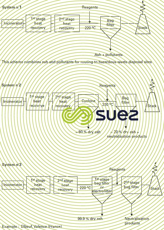
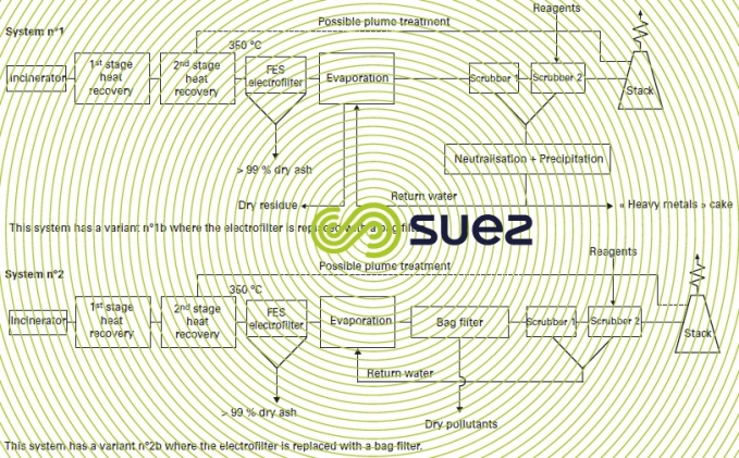
Figure 42 describes the system as a series of variants. It addresses the various forms of pollution as follows :
dust
This pollution is mainly captured during the first dust removal stage :
- cycloning (figure 42 system 2) (or multi-cycloning) has the advantage of not being affected by stringent temperature constraints; on the other hand, the dust capture rate is very closely linked to the particle size of the dust and, depending on this particle size, the reduction rate will fluctuate between 50 and 90% and must, therefore, be preferred for lower dust loading levels;
- hot and dry electrofilter (figure 42 system 3) (maximum temperature of approximately 350°C); depending on the target reduction level, this electrofilter can have several fields in series and its reduction rate will range from 98 to 99.5%);
- bag filters constitute equipment that can be regarded as the absolute filter that will always ensure that the level of incoming dust remains below 10 mg · Nm–3. Depending on the nature of the bags, the temperature restrictions will change; for continuous operation, this limit will be 220°C for Teflon backed filters.
halogen, sulphur, volatile heavy metal, dioxin pollution
This pollution is treated simultaneously using neutralising agents :
- sodium bicarbonate;
- lime:
- powdered activated carbon…
- «sorbalite» (mixture of lime and an adsorbant powder).
Bicarbonate and lime are neutralisation reagents used on halogen and sulphur pollution; the powder adsorbant adsorbs volatile heavy metals, dioxins and furans. Given the dry reaction principle and the gas medium with short contact times, provisions must be made for extra reagents over and above the stoichiometry. This excess will vary depending on the nature of the reagents (1.5 for bicarbonate; 3 for lime; however, the reaction with lime is a molar reaction and, therefore, 2 moles of bicarbonate will be required for the same neutralisation effect).
We should also note the following :
- sodium bicarbonate requires the inclusion of a preparation unit comprising a raw product storage and crushing unit to ensure that the sodium bicarbonate has the requisite level of reactivity;
- given the cost involved in disposing of the final waste, in some cases, it might be advisable to equip the unit with a neutralisation cake processing system consisting in re-dissolving the bicarbonate. The aqueous fraction is recycled to the plant inlet and all that remains is a final residue that mainly consists of the adsorbantcontaining heavy metals.
plume
One of the advantages of the dry process is that it does not emit a plume (except, if applicable, under very low hygrometry conditions and temperatures well below 0°C).
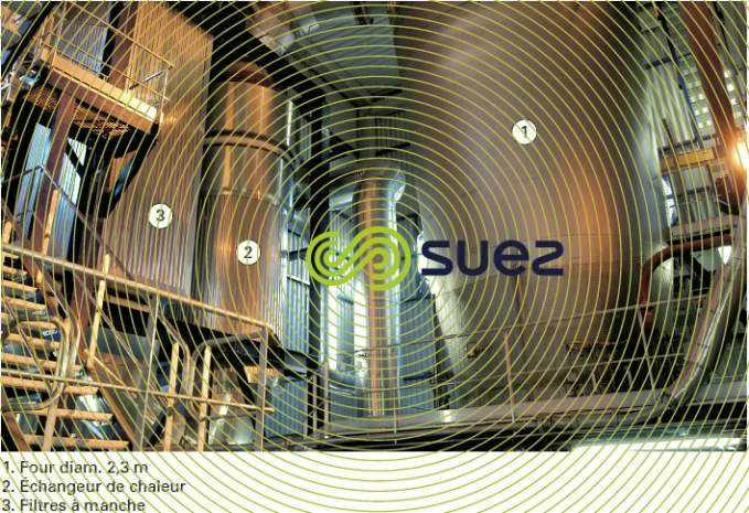
Photo 19 shows the Elbeuf plant with its 2.3 m diameter (1) fluidised bed incinerator, heat exchangers (2) and two bag filters in series (3).
the semi-wet system
In fact, this is a hybrid system that bridges the wet and dry systems and attempts to retain the benefits and limit the drawbacks of both systems.
The wet system has two major drawbacks:
- it produces ash-laden water that is particularly penalising when the dust level is very high (fluidised bed);
- the need to process the blowdown produced by the different wash stages.
The dry system has two major drawbacks:
- the flue gases have to be cooled before going into the treatment line; this cooling requirement is particularly stringent when bag filters are used;
- the excess reaction stoichiometry characteristic of the dry system represents a significant running cost.
In order to offset these drawbacks, the semi-wet process (figure 43) is, in fact, a zero blowdown wet process.
Therefore, it consists in placing, in front of the wet process (scrubbers), a reaction column used to spray and evaporate blowdown. This system is only feasible when the sensible heat contained in the flue gases can compensate for the evaporation and superheating of the water contained in the blowdown. The crystallisation salts are recovered from the base of the column or in the bag filter. This principle can only apply to flue gasesthat contain little dust. Therefore it is well suited to pyrolysis processes (in this case, it is very cost-effective both in terms of investment and in terms of reagent costs); it is not at all well suited to fluidised bed type incineration applications.
In order to render this system compatible with high dust loads, a preliminary dust removal system has to be inserted in front of the column (e.g. hot electrofilter) – see systems 1 and 2 (figure 43).
processing nitrogen oxide (NOx) pollution
Regardless of the systems described above, they will not remove pollution linked to nitrogen oxide (NOx). For this purpose, all processes use an ammonia solution that reacts with NOx according to the following general reaction :


This reaction is catalysed in two ways :
- either at high temperature (approximately 900 °C): homogenous catalysis called SNCR;
- or at low temperatures (200-300 °C) heterogeneous catalysis called SCR (catalyst supported on ahoneycomb that is crossed by the flue gases).
The SNCR method, when the heat process allows, is simple to use. All that is required is to inject a solution of ammonia or a urea salt into the process zone at a point where the flue gas temperature is close to 900°C. In the wet process, any excess of NH3 will automatically be neutralised. In the dry system, it is assumed that a scrubber will be included downstream from the bag filter which, to a certain extent, reduces the specific benefits associated with this process (e.g. absence of plumes…).
In the case of dedicated fluidised bed incinerators, a 200 mg · m–3 emission level is routinely met without the need for a specific NOx remover. When the nature of the sludge or the operating conditions do not allow this limitation to be met, feedback has demonstrated that it is reasonable to expect a 50% reduction in NOx levels. When a 50% reduction is not enough for complying with statutory thresholds, an SCR solution must be implemented.
Implementing the SCR solution is a far more complicated solution. This solution must be placed downstream from the flue gas treatment system because the catalyst service life will be significantly affected when it comes into contact with impurities (mainly SO3) contained in the unscrubbed flue gases. When applied to a wet or semi-wet treatment, installing an SCR requires :
- the installation of a system of thermal oil exchangers used to remove the energy contained in the upstream flue gases so that this energy can be recycled downstream for preheating to the requisite temperature by the SCR (on the other hand, this system is not required for dry processing);
- a high head loss requiring the installation of a second extractor fan;
- a booster burner used for rigorous control over the temperature of the reaction;
- as in the case of the SNCR, storage for the ammonia solution or the urea salt.
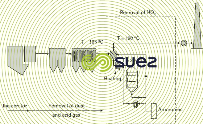
The fifure 44 illustrates an SCR system twinned with dry processing.
Bookmark tool
Click on the bookmark tool, highlight the last read paragraph to continue your reading later
