


dedicated fluidised bed incineration: the Degrémont® thermylis-htfb incinerator
Reading time:sizing
The following constitute the basic data required to define the heat balance for an incinerator:
- the mass flow rate of the sludge to be processed expressed in kg · h–1;
- the dry solids content of sludge to be treated (%);
- the organic matter content (%);
- the NCV of organic matter (kJ · kg–1 of OM); if this figure is not known, it can be calculated providing that we have an analysis of the elements constituting the organic matter (C, H, O, N, S) – e.g. the Dulong-Petit formula:
GCV = 81.3 C + 345.5 (H-O/8) + 22.2 S and NCV = GCV – 54 H.
The main criteria (physical or statutory) that have to be included when calculating the thermal balance are:
- temperature in the bed: 800 °C minimum;
- temperature at the freeboard: 850 °C;
- contact time in the freeboard: 5 seconds minimum;
- fluidisation rate at the grate: 0.9 m · s–1;
- fluidisation rate at the top of the bed: 0.85 m · s–1;
- combustion product velocity at the top of the freeboard: 0.65 m · s–1;
- expanded sand bed depth: approximately 1.5 m;
- flue gas O2 content: ≥ 6 % with dry gas;
- fluidisation air temperature that must not exceed 650°C in the wind box.
We can use these bases to establish a heat balance that will primarily determine:
- the air flow required to oxidise the organic matter fed in (including a 40% excess). This flow must allow for the requisite fluidisation rate and for temperature and pressure corrections at the grate. It will determine the grate’s internal section and, consequently, the incinerator’s internal diameter at the grate;
- the heat balance which is the result of an iterative calculation involving the fluidisation air temperature, the oxygen level and the 850°C temperature in the freeboard. Its result defines:
- the top-up fuel required;
- the composition of the combustion products;
- the temperature profile;
- the incinerator’s main dimensions;
- the main characteristics of the exchanger responsible for heating the fluidisation air using the sensible heat from the combustion gases.


the heat balance
The heat balance is calculated using specific software where the main equations are as follows:


With the following inputs:
QAB = the amount of heat contributed by the circulating air (air used to cool the areas exposed to major heating: water, auxiliary fuel, sludge… injection pipes).
QAF b+g = amount of heat contributed by the fluidisation air required for organic matter combustion (less the circulating air).
Qs(e) = amount of heat contributed by the sand flow intended to compensation for attrition losses.
Qb+g = amount of sensible heat contributed by the incoming products.
Qcomb b+g = quantity of heat contributed by total combustion of the organic matter.
Qca = amount of heat contributed by top-up fuel combustion.
QAFca = amount of heat contributed by the fluidised air required for top-up fuel combustion (to be added to fluidisation air).
With, as outputs:
Qashes = sensible heat removed with ashes.
Qdischarged gas b+g = sensible heat from flue gases generated by the combustion of organic matter (including excess air).
Qdischarged gas ca = sensible heat from flue gases generated by the combustion of top-up fuel.
Qs(s) = sensitive heat from sand particles entrained in the flue gases.
Qlosses = heat lost through thermal losses.
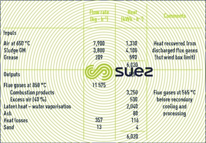
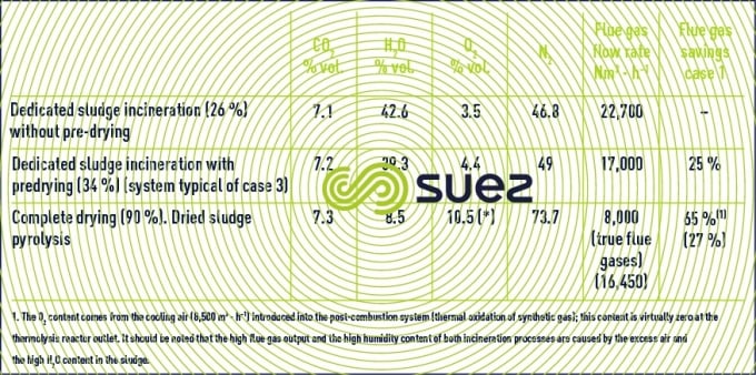
Table 9 comprises a simplified heat balance applied to dewatered sludge. The importance attributed to preheating air should be noted: Approximately 22 % of calories injected into the furnace, the amount of latent heat contained in the vaporised water (34 %) and the excess air (9 %) in the lost heat.
Note: the same sludge, were it to contain 22 % dry solids contents, would inject 740 L · h–1 of extra water and require approximately 65 L fuel · h–1!
general operating principles
general operating principles
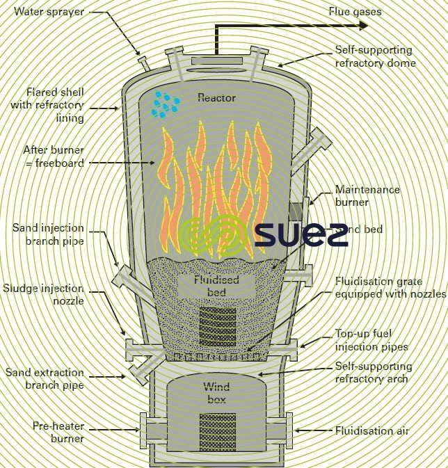
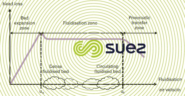
The fluidised bed incinerator is based on the principle whereby pre-calibrated sand particles form a suspension with a current of pre-heated air. Figure 28 illustrates the sand fluidisation area using air (see Fluidisation). There is a ratio of approximately 1 to 10 between ut and uo and, clearly, the characteristic curve depends on particle size and on the density of the sand used for the bed. Fluidised bed physics and thermodynamics have been described in depth in the reference works (Fluidisation engineering, Daizo Kunii and Octave Levenspiel, Fluidisation, Max Leva).
The degremont® Thermylis-HTFB fluidised bed incinerator is a dense fluidised bed unit without bed overflow. A fluidised sand bed taken to incineration temperature (800-850 °C) constitutes an extremely turbulent medium where heat exchanges reach extremely high transfer coefficients. The dewatered sludge injected into this bed is very rapidly disintegrated by the turbulence of the sand and evaporation takes place instantly. At the same time, the organic matter undergoes combustion, using the fluidization air as the comburent.
As there is no bed overflow, the expanded bed depth remains stable (give or take sand losses caused by attrition). In effect, the particle size of the mineral matter in the sludge is very small compared with the size of the grains forming the sand bed. Therefore, all mineral ash is carried away pneumatically into the upper section of the incinerator and then through the flue gas evacuation stacks (fly ash).
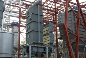
the incinerator construction principle
The incinerator consists of a metal shell with a refractory brick lining. It comprises six sections that are piled up from the bottom to the top, constituting a selfstabilised and self-supporting system.
the wind box
The wind box has a cylindrical section. The fluidisation air delivered by the blower enters into the wind box via an air duct connected to a wide radial opening. If this air arrives pre-heated to a temperature below 250 °C, we have a cold wind box; above that temperature, we have a hot wind box. Most of the fluidised bed furnaces that incinerate sludge use the hot wind box design.
This wind box has a silico-aluminous type refractory lining with an insulating layer between the shell and the actual refractory lining. The fluidisation dome bears on the top section of the wind box. The wind box has a burner (that may be retractable if necessary); this burner is used for preheating during the start-up procedures (photo 18).
- The fluidisation dome
This is the incinerator’s essential component because fluidisation air is distributed through this dome. In the hot wind box version, the dome is made up of a series of rings of standard special refractory bricks (see detail, photos 16 and 18). These rings are under compression and form a self-supporting dome. Each of the standard special refractory bricks is crossed by a vertical hole that houses the fluidisation nozzle. The number of nozzles and their section define an open surface area that in turn defines the head loss through the fluidisation dome.
This head loss ranges from approximately 50 to 60 mbar. In the cold wind box version, the fluidisation dome consists of a "sandwich" made up of a concave sheet of refractory steel onto which the fluidisation nozzles are welded. This steel sheet is set in a refractory concrete coating;
- Fluidisation nozzles
In most cases, they are shaped like a mushroom with a circular cap. The air velocity through the nozzle is equal to approximately 40 m·s–1; this nozzle, constructed of refractory cast iron and anchored into the hole in the refractory brick support, is a key point in the incinerator’s construction. Any nozzle loss will create a serious malfunction because fluidisation sand will pass direct into the wind box and fluidisation will be adversely affected.
the actual fluidisation zone
The fluidisation zone is the expanded sand bed depth which, in most cases, goes up to between 1.5 and 2 m. This zone also has a silico-aluminous refractory brick lining with insulation between the refractory lining and the metal shell. Sludge feed and top-up fuel (diesel, gas, biogas) inlets are located in this zone.
the expansion zone
Designated freeboard, it is flared in shape in order to allow it to cope with the increase in gas products created by both temperature and completed combustion; the freeboard is also used to gradually reduce entrainment velocity in order to de-fluidise the finest sand particles. This expansion zone is also used for postcombustion and provides combustion products with a very long contact time (at least 5 seconds) which, under any circumstances, ensures that waste incineration standards are met. Top-up sand, making up for losses through attrition, is fed into this zone.
the upper dome
It comprises standard special refractory brick rings that form a self-supporting dome. It is supported by the outer expansion zone skin. The centre of this dome is hollow and forms the base of the combustion product outlet stack. Water injectors are mounted in this dome for temperature regulation (safety).
connecting flue
Linking the incinerator outlet and the recovery exchanger inlet, this flue also has a refractory lining and must incorporate an expansion joint.
the outside of the incinerator
It is enclosed within a series of walkways that are independent of the incinerator structure. At least two levels of walkways are required: one at sludge and top-up fuel inlet levels and another over the top of the dome for access to the combustion product evacuation stack.
energy consumption optimisation
targeting heat self-sustainability (figure 29)
Energy consumption optimisation is an essential point in the design of a dedicated incineration unit: heat self-sufficiency is automatically targeted when seeking to optimise the recycling of combustion product sensible heat. This constitutes a compromise between minimised top-up fuel consumption on the one hand and investment and operating costs on the other.
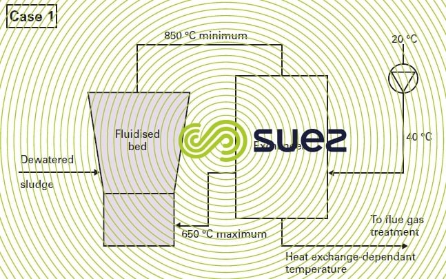
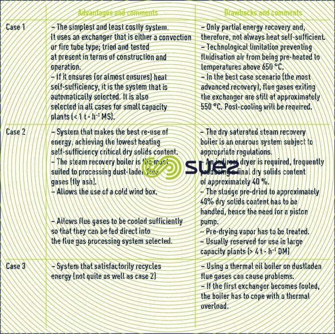
case 1 (figure 30)
Fluidisation air pre-heated by the partial recycling of exhaust gas sensible heat will suffice. However, the 650°C temperature is the maximum we can reasonably expect.
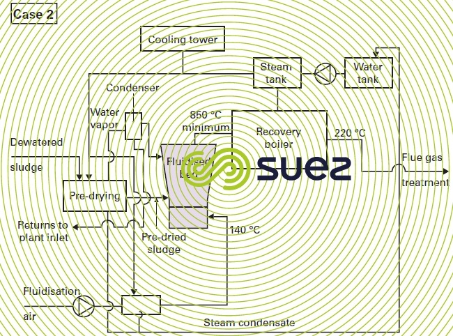
case 2(figure 31)
The maximum amount of energy contained in flue gas sensible heat must be recovered. In this case, we need to use a recovery boiler linked to a dryer. Accordingly, a large proportion of the water contained in the sludge is neither evaporated nor superheated in the incinerator.
case 3 (figure 32)
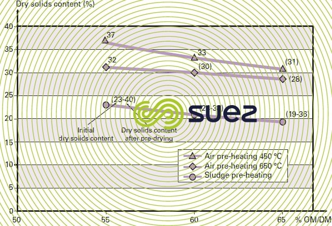
This also refers to a comprehensive recovery of sensible heat from combustion products but in a combined system. As in case 1, an exchanger is included to preheat fluidisation air and then a thermal oil boiler is installed, producing oil at temperatures of approximately 200 °C and also partially drying the sludge. In this configuration, lines 1 and 2 in table 9 demonstrate the major impact made by the incoming sludge water content. In the example quoted, a very partial pre-drying (26 → 34 % DM) enables us to save 5,700 m3 ·h–1 of flue gases (water vapor), i.e. 25 % of flue gases and to achieve a slight energy surplus instead of inputting 2.7 MWh · h–1 in the form of top-up fuel.
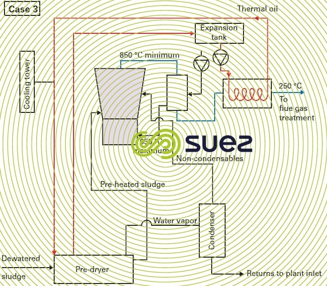
This design avoids the need to go through the vapor boiler which creates major construction and operating constraints. The thermal oil boiler can be replaced with a pressure water boiler if necessary.
Each of the above three cases has advantages and drawbacks that need to be addressed before making any choices and before moving on to project performance engineering. Table 11 provides a general overview of the major advantages and drawbacks of each of these solutions.
the technologies applied to energy recovery processes
fluidisation air pre-heating exchanger
Exclusively multi-pass crossed tube convection exchangers: fluidisation air travels through the tube bundles and the flue gases through the exchanger grill.
These exchangers were systematically used in the past and caused operating problems induced by a loss of sealing properties where the tubes cross through the exchanger grills. These exchangers are sensitive to dust loading, especially the inlet unit where scaling phenomena can occur, especially when flue gases are overheated to a temperature close to the ash fusion point (affected by the P content).
Exchangers using fire tubes only: this system operates in the opposite way to the previous one: the flue gases travel through the tubes while the air travels through the exchanger grill. These systems are more compact and of a simpler construction. However, we need to check on the design of the expansion joints on the fire tubes and on the fact that these are not fouled by ash. It must be possible to clean fire tubes during major maintenance operations.
Radiant/convection exchangers: these exchangers have a twin wall that is used as a radiant unit. The flue gases first travel through this radiant section where they release a proportion of their sensible heat; thus, the convection tube bundle is placed under less heat stress.
Radiant fire tube exchangers: same principle as above with the use of fire tubes.
In our most common applications (case n° 1), we recommend using fire tube exchangers.
steam recovery boiler
Unlike the boiler applications in household waste incinerators (superheated vapor with turbine for generating electricity), this is just a simple natural circulation boiler that produces dry saturated steam. This system must include an air coolant for dissipating any excess steam produced and for systematic use during heating operations when the incinerator’s pre-dried sludge feed has not been started up. In effect, sludge that has been pre-dried to within a wide range of dried solids content (35 to 65%) cannot be stocked and extracted.
thermal oil boiler
These are classic pin exchangers that may have to be protected upstream by partial dust removal (e.g. cycloning).
industrial concern
The fluidised bed incinerator is not very flexible when it comes to sludge flow fluctuations, at a constant heat balance, (approximately 15% flexibility in relation to nominal loading).
On the other hand, it is very flexible to operate. It can cope with frequent shutdowns and start-ups, in particular, allowing us to consider an operating mode where incineration is put on standby during evening and weekend shifts.
A certain number of automated controls are required to control this process; in particular, combustion quality is controlled by a control algorithm and, therefore, does not require the control room to be permanently manned. However, a human presence “in the vicinity” is always required so that speedy action can be taken in the event of a malfunction (e.g. power failure).
Bookmark tool
Click on the bookmark tool, highlight the last read paragraph to continue your reading later
